


Abstract
Technological innovations have revolutionized spine surgery. There are a variety of image-guidance systems and navigation options including robotics and augmented reality. These devices provide the opportunity for increased safety and efficiency in surgery. There are advantages and disadvantages to each approach to spinal instrumentation. In this article, the author reviews his experience with visible light navigation using a 7-dimensional (7D) machine vision system and reviews the use, strengths, and weaknesses of this method of spinal navigation.
This study is a retrospective cohort investigation of 150 consecutive patients who underwent spinal instrumentation placement utilizing visible light navigation. The objective was to determine the utility of the navigation system and its strengths and weaknesses as well as to assess patient safety when screw placement is performed with visible light navigation in place of C-arm localization. Visible light navigation was found to be effective and efficient, enhancing screw placement and decreasing surgical time. There were no complications in this series of patients and no instances of symptomatic screw malposition.
INTRODUCTION
Spinal instrumentation has historically been placed with a combination of anatomic landmarks and C-arm visualization. Evolution of technology has evolved to fluoroscopy-based 3-dimensional (3D) imaging and intraoperative computed tomography (CT) images with freehand or robotic screw insertion. Most of these systems are amenable to traditional open surgical techniques or to minimally invasive or minimal-incisional approaches. Navigation has increased the safety and efficiency of spine surgery, especially in thoracic spine stabilization, where the smaller pedicles and presence of the spinal cord increase the risk of neurologic injury. Navigation is especially useful in deformity surgery, where there is frequently not only the abnormal orientation of spinal segments but also congenital abnormalities at the vertebral level, such as absent or hypoplastic pedicles.
Use of 2D fluoroscopy with C-arm has been a standard technique. Advantages include wide availability and relatively low cost. The disadvantages include radiation exposure for the operative team, as well as an incidence of pedicle breach reported from 5% to more than 30% of instrumented pedicles.1
3D platforms typically couple navigation software with intraoperative CT or O-arm imaging. These systems significantly increase the accuracy of screw placement vs conventional fluoroscopy. Mason et al reported accuracy of 95.5% for 3D navigation vs 68% for conventional fluoroscopy.2
There are a number of disadvantages to 3D systems. These systems tend to be costly, with 3D fluoro-based machines (O-arm, Ziehm, Orbic 3D) ranging in cost from $300,000 to $600,000 and intraoperative CT scanners with price tags over $1 million.3 Navigation software and operational personnel can add an additional $700,000 to initial costs.3 These systems also require one or more intraoperative scans, which can significantly increase total operative time and expose the patient and potentially the staff to significant radiation.4
The visible light navigation system is distinctly different than other currently used navigation systems. Intraoperatively, navigation is based entirely off of visible light images correlated to a preoperative CT image. A tracking array is attached to a spinous process, and an image is obtained with a visible light “flash.” The cameras and trackers are incorporated into a portable overhead light. There is only a need for intraoperative fluoroscopy if needed for determination of spinal level. Once positioned over the wound, the entire process can easily be controlled by the surgeon using a foot pedal. In the present article, I describe the visible light navigation system and report my experiences and patient outcomes using this system in my practice.
TECHNICAL BACKGROUND AND MACHINE VISION WORKFLOW
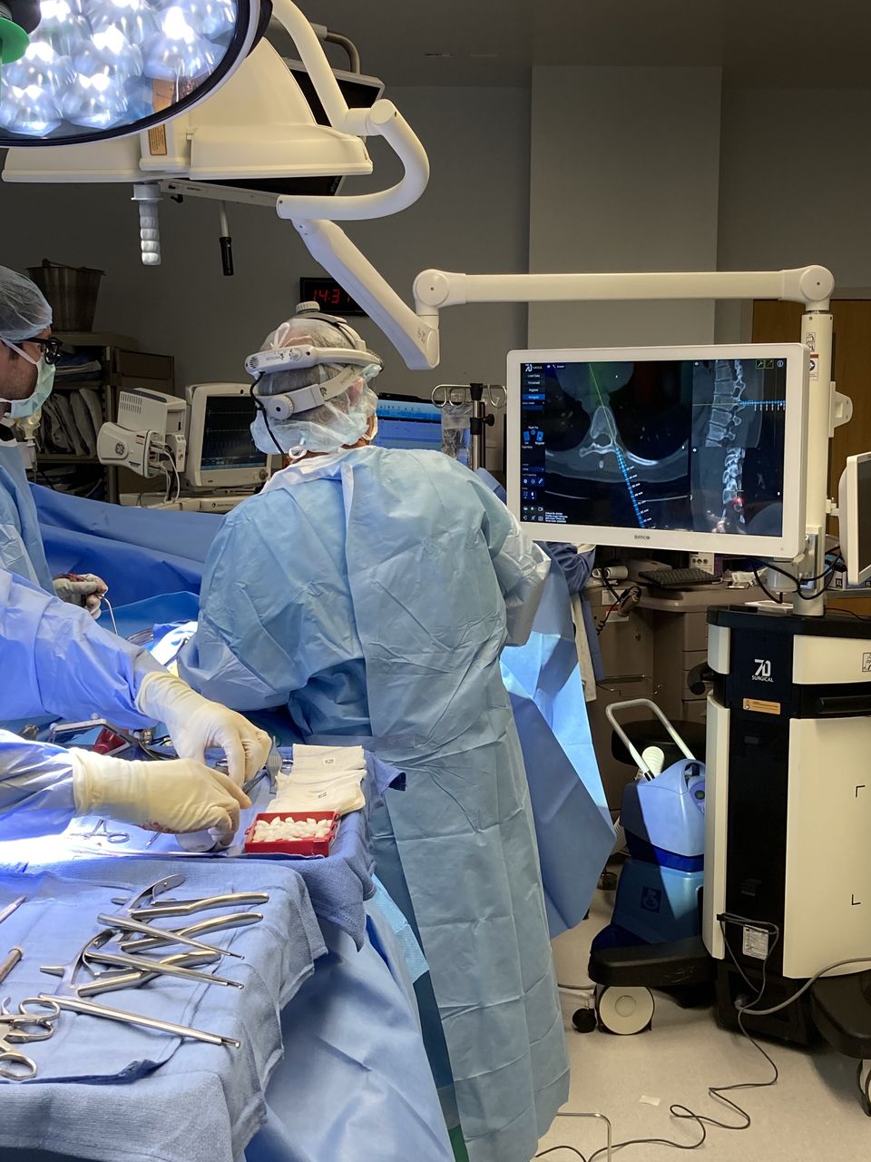
Machine vision has been utilized in a variety of nonsurgical applications but recently has been innovatively expanded into the spine surgery field. The 7D Surgical System (Figure 1) uses a specific machine vision called structured light imaging, which combines a light projector with 2 stereoscopic video cameras. These nonionizing structured light cameras acquire a precise 3D image of the patient’s exposed surface anatomy and register it to a preoperatively acquired image (such as a CT image) using advanced machine vision algorithms. This application of machine vision structured light has been expanded into both spinal and cranial surgery.

The 7D Surgical System machine.
The workstation consists of a small, mobile computer with an attached, movable arm. This arm consists of a surgical light source, 2 stereoscopic video cameras, a structured light projector, and an infrared camera system for tracking navigation tools. The small size of the workstation allows for flexibility in its positioning. It is placed adjacent to the surgical table, and the arm is adjusted to place the system head directly over the surgical field. The surgical light on the system head ensures adequate illumination of the surgical field, reducing the need for the standard ceiling-mounted surgical lights. If standard lights are used during the surgical exposure, they need to be directed away from the field during the navigation process because of their potential to interfere with the structured light imaging process.
The navigation workflow for the system is initiated by loading a preoperatively acquired CT image of the appropriate spinal levels onto the workstation and threshold appropriately to maximize visible bony landmarks. The CT image requires 1-mm cuts of soft tissue windowing only and should be performed from 1 level above to 1 level below the planned surgery.
The system requires exposure of the vertebral segments as in traditional open surgery. Typically the exposure is of the midline structures to the lateral border of the facet joints or medial transverse process. There is no need for radical soft tissue release; the facet capsules can be preserved if desired.
The spinal levels to be registered are preidentified by selecting 3 approximate points on the preidentified level for registration. The system head is then aimed toward the exposed surgical anatomy with the attached reference array with the aid of laser guidance. Two stereoscopic video images of the field are displayed on the workstation monitor. Once aimed accurately, the surgeon is autonomously able to trigger the structured light projector in the system head to briefly project a linear light grid pattern onto the surgical field. As this occurs, the 3D surgical anatomy distorts the lines of the light pattern. The degree of this distortion is detected by the overhead stereoscopic video cameras. The color system captures >~1,000,000 data points over a 40 × 30 cm surface area, yielding a resolution of 4 to 6 points per square millimeter.1 The specific distortion of the light pattern is then used to calculate surface depths to reconstruct the 3D topography of the exposed surgical surface anatomy.1 Three points should approximately match the preoperative image, and this reconstructed image is then rapidly correlated to the preoperative CT image and the navigation can proceed.
This machine vision registration requires only seconds allowing registration to be easily repeated if the reference array is inadvertently or accidentally moved.1,3 To ensure accuracy of the navigation, the reference array can also be moved along and reregistered to several levels.5 In cases where bony anatomy may be missing, it is also possible to register to previous hardware. To reregister using the 7D Surgical System, this requires an additional projection of the light pattern grid onto the surgical field with the repositioned reference array. The updated image reconstruction is reregistered to the stored image, and navigation can resume. This ability to rapidly reregister allows for each vertebrae to be individually registered, optimizing navigational accuracy.1,3 This is in contrast to other navigation systems, where repeating registration would require repeating the imaging process by bringing the imaging system back into the room, repositioning it, and obtaining updated images. This process would add significant time and radiation exposure to the procedure.
Following registration, visible light navigation functions like other systems. Tools are trackable using infrared cameras in the system and include an awl, a pedicle probe, a drill guide, and a universal tracking device that can be attached to any tap or screwdriver. Multiplanar images are projected in real time, indicating the selected entry points and trajectories through the spinal anatomy. An additional unique feature of the 7D Surgical System is the option of using augmented reality (AR) to facilitate accuracy under circumstances when tool tracking is not feasible. This AR software has been added to allow the surgeon to project “safe” zones and trajectories through selected pedicles.6 When a navigated trajectory has been selected by the surgeon, a virtual line along the trajectory can be projected onto the system’s video monitor and preserved during screw insertion. Aligning a nontracked tap or screwdriver with the virtual line on the live video feed preserves the screw insertion accuracy.7
REVIEW OF CASES
I reviewed my first 150 consecutive cases of spinal surgeries using the 7D Surgical visible light navigation system. These cases were performed in a single institution where I was the primary surgeon. The patient cohort consisted of 92 women and 58 men. The age range was 17 to 84 years; the average age of treated patients was 64.5 years.
All cases were elective. The primary indication for surgery was kyphoscoliotic deformity in 11 patients. Three cases were for fracture; the primary indication was spinal stenosis with deformity and/or instability in the remaining patients. Fifty-nine patients had had a prior operation at a current operative level.
There were 5 cervicothoracic cases, 1 thoracic case, 21 thoracolumbar cases, and 123 cases limited to the lumbar or lumbosacral spine. A total of 534 levels were instrumented, which was an average of 8.9 levels per patient with a primary indication of deformity and 3.1 levels for all other patients.
Illustrative Case 1
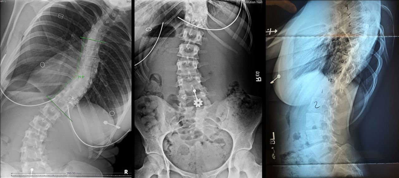
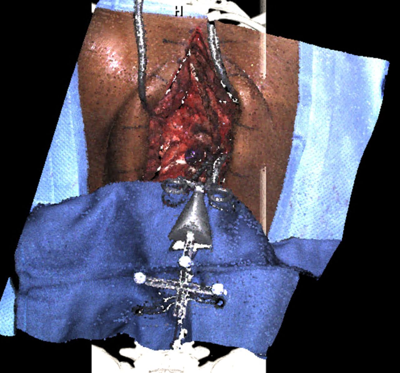
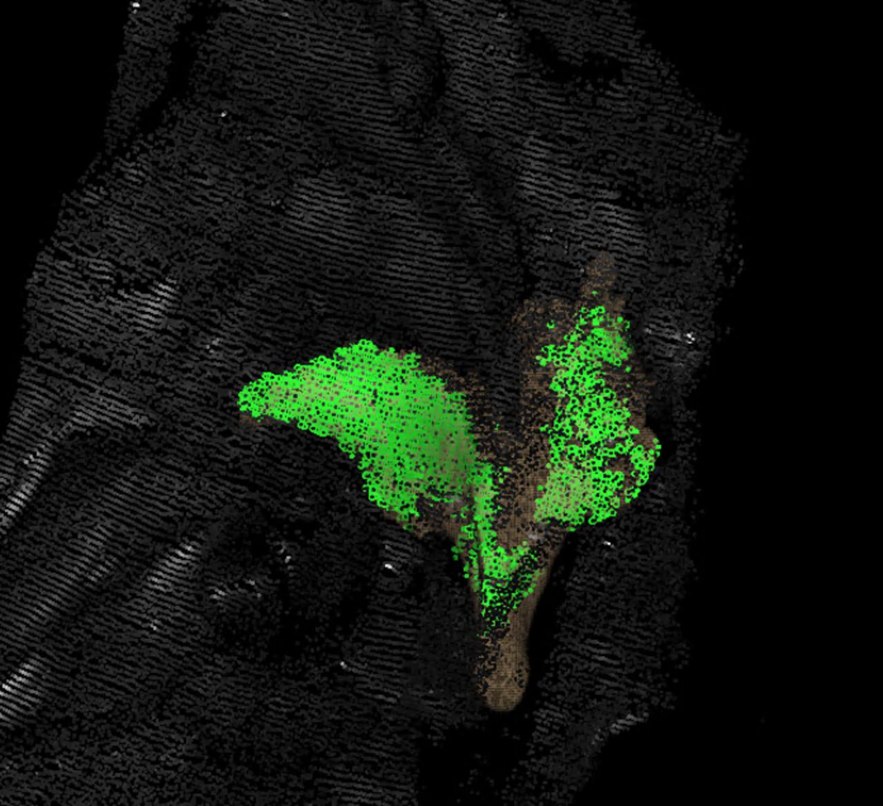
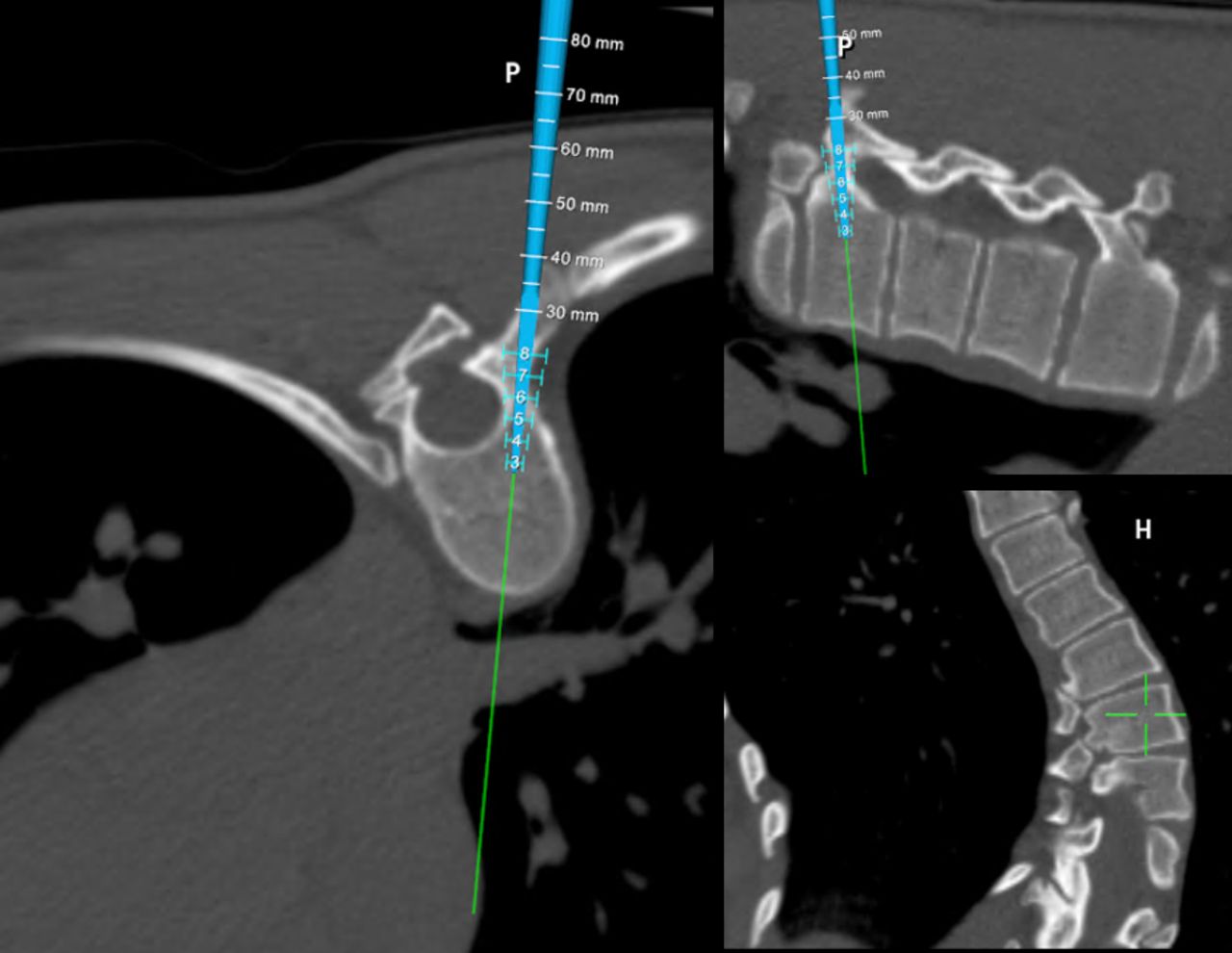
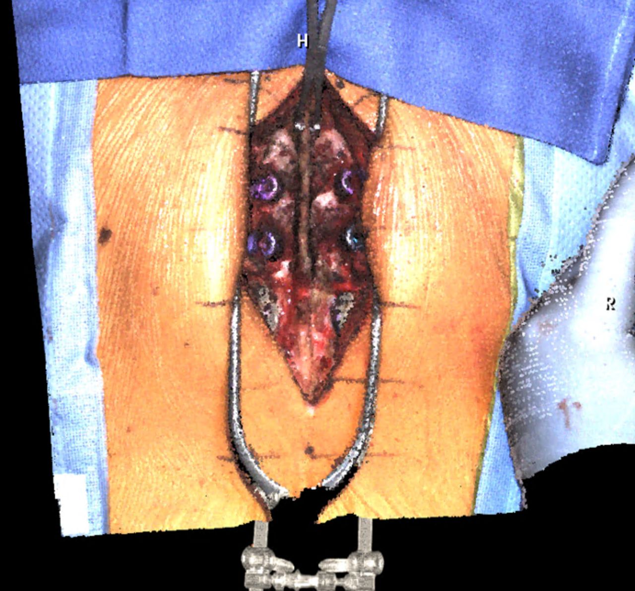
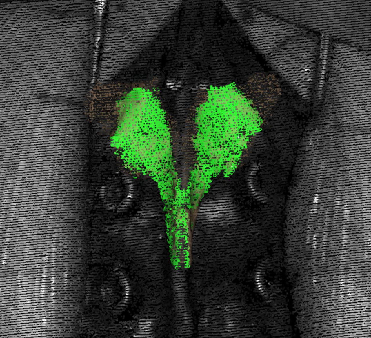
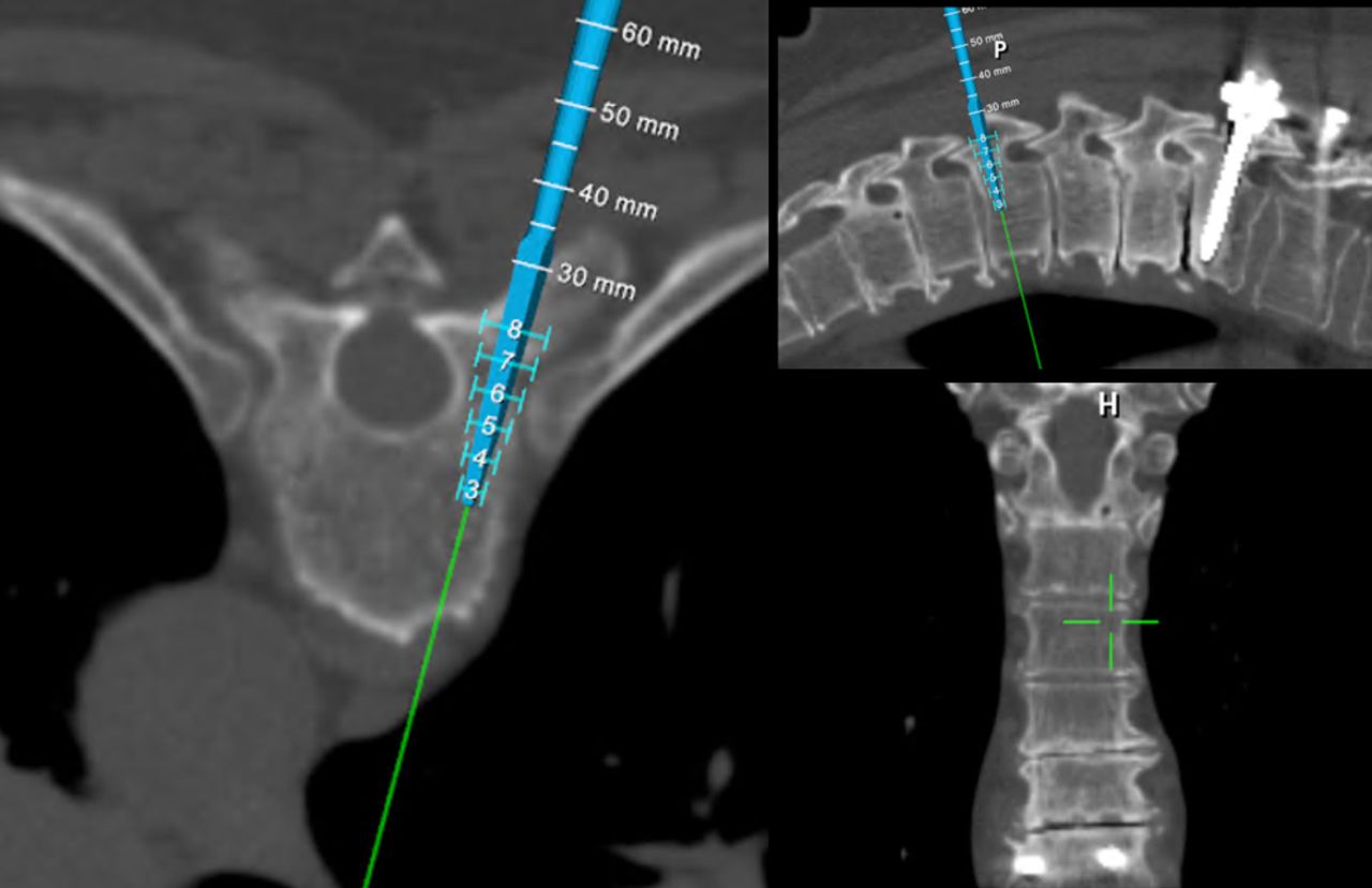
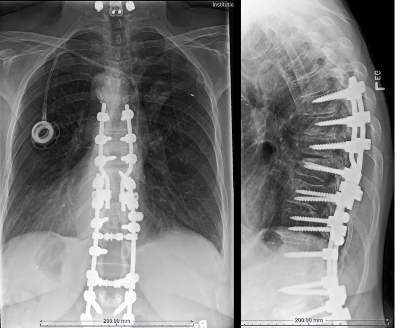
Case 1 is a 21-year-old woman with Scheuermann kyphosis (67° T9-L3) and painful progressive scoliosis (47° T9-L5) (Figure 2). She underwent instrumented arthrodesis of the thoracolumbar spine with machine vision navigation of all screws. Intraoperative machine vision image is shown in Figure 3, and points matched to the preoperative CT scan are shown in Figure 4. Intraoperative navigation images are shown in Figure 5, and postoperative radiographs are shown in Figure 6.

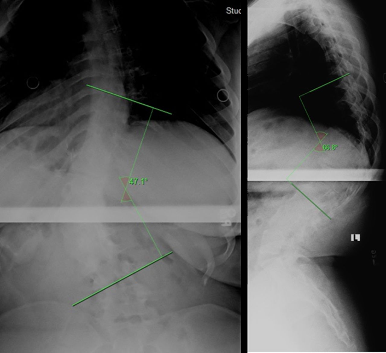
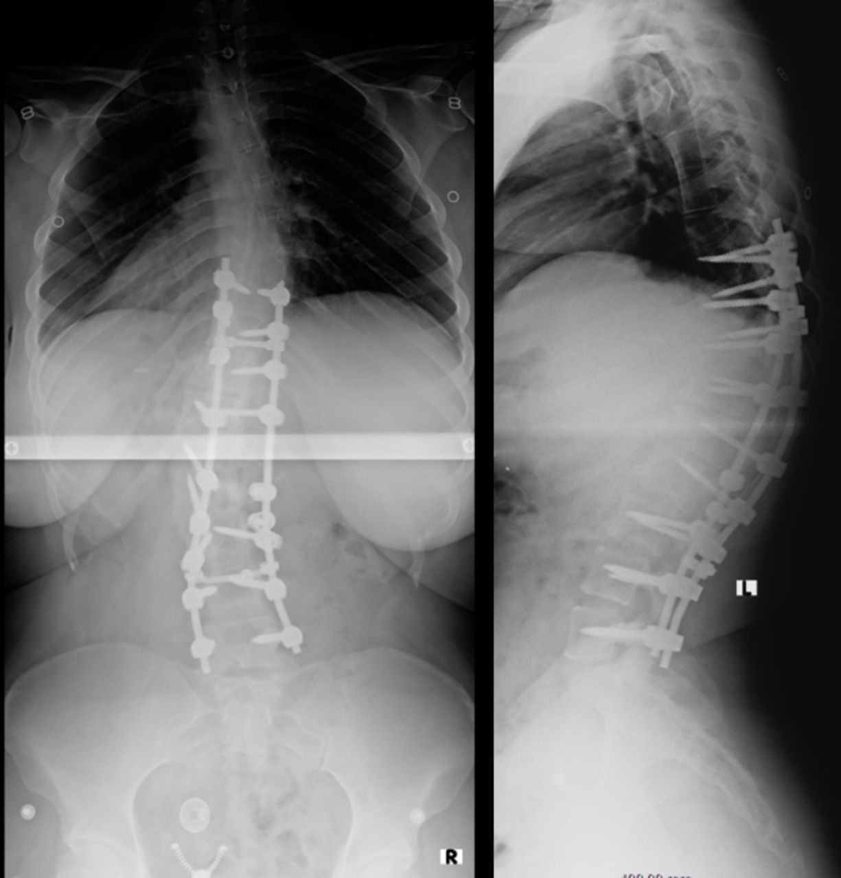
Preoperative anteroposterior and lateral thoracolumbar spine radiographs of the patient in case 1. Cobb angle and kyphosis measurement shown.

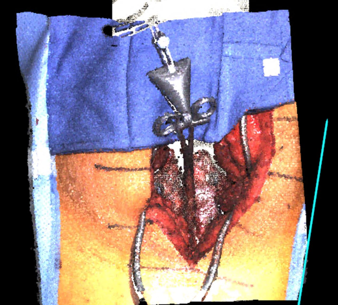
7D Surgical System acquired image of surgical field of the patient in case 1.

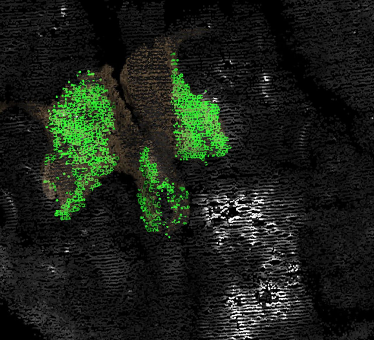
A total of 1641 points matched to preoperative computed tomography at L3 in the above image for the patient in case 1. After the “flash” of structured light, the machine matches those points to the preoperative scan during registration. The image above is displayed on the monitor. Each green dot is a matched point, providing rapid visual feedback as to the adequacy of the registration.
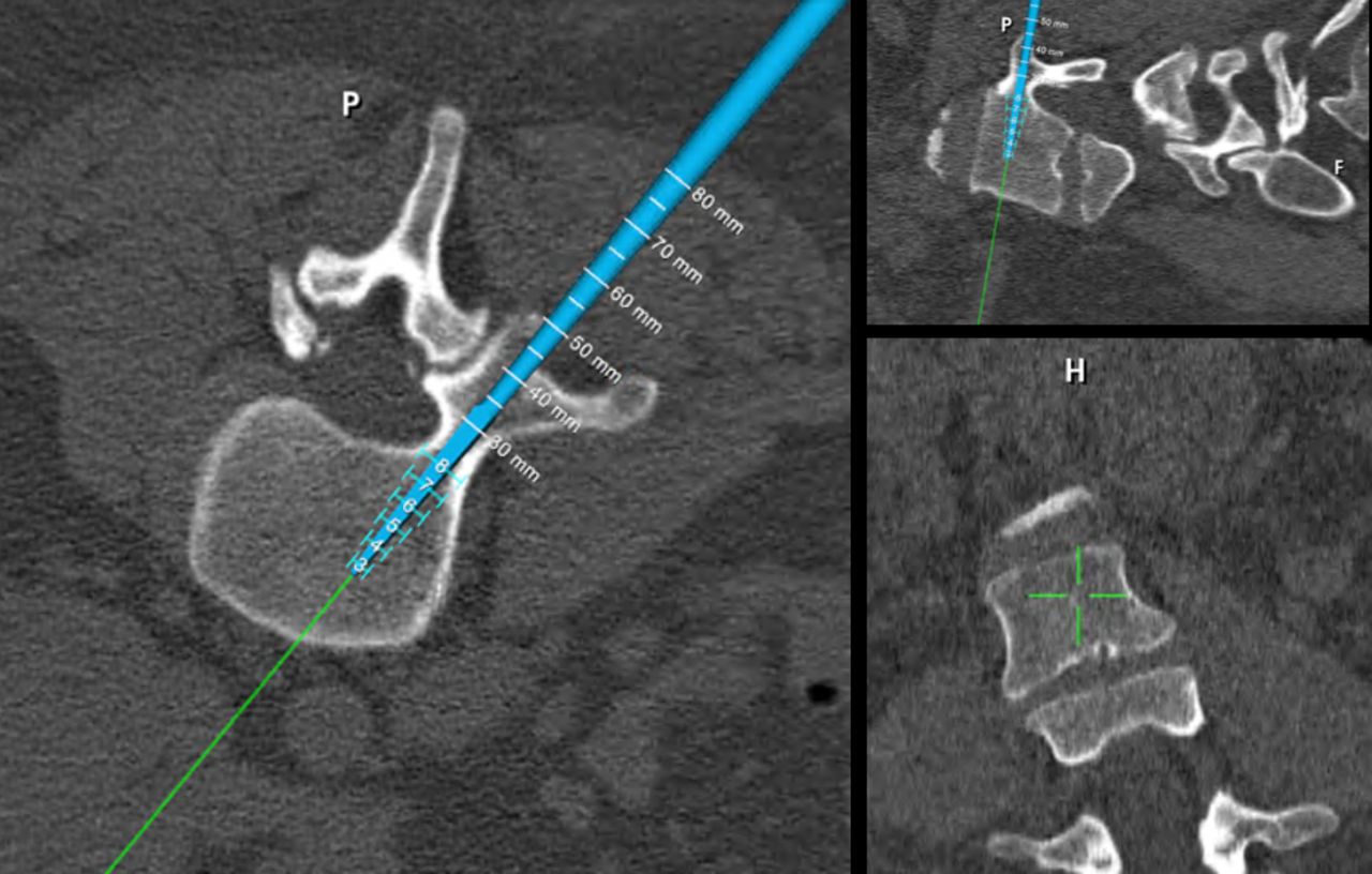
Navigation of the left screw for the patient in case 1. Note real-time measurement of vertebral dimensions, thus eliminating the need for preoperative templating of pedicle dimensions. P = posterior; H = head.

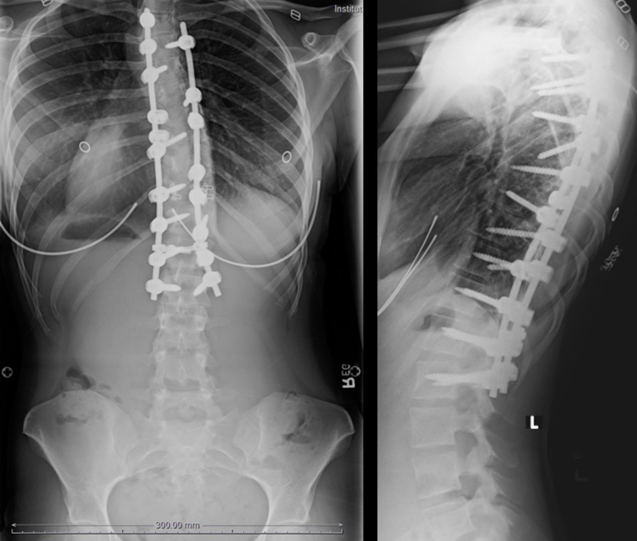
Postoperative anteroposterior and lateral radiographs of the patient in case 1.
Illustrative Case 2
Case 2 is a 68-year-old man with cervical spinal stenosis with advanced myelopathy. His spasticity had reached the point to which he had trouble feeding himself. He underwent posterior decompression and stabilization with lateral mass screws at C3-C6 and pedicle screws at T1 and T2. Preoperative radiographs are shown in Figure 7, a structured light intraoperative image in Figure 8, and points matched to CT in Figure 9. Figure 10 is the intraoperative navigation image. Postoperative radiographs are presented in Figure 11 .

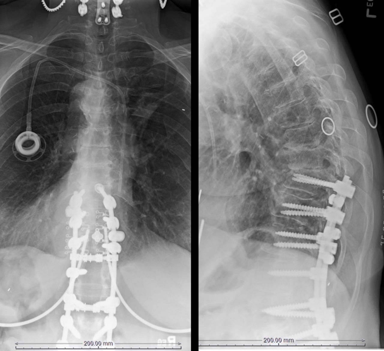
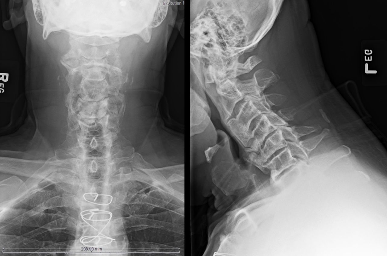
Anteroposterior and lateral radiographs demonstrating advanced spondylosis with cervicothoracic kyphosis in the patient described in case 2.

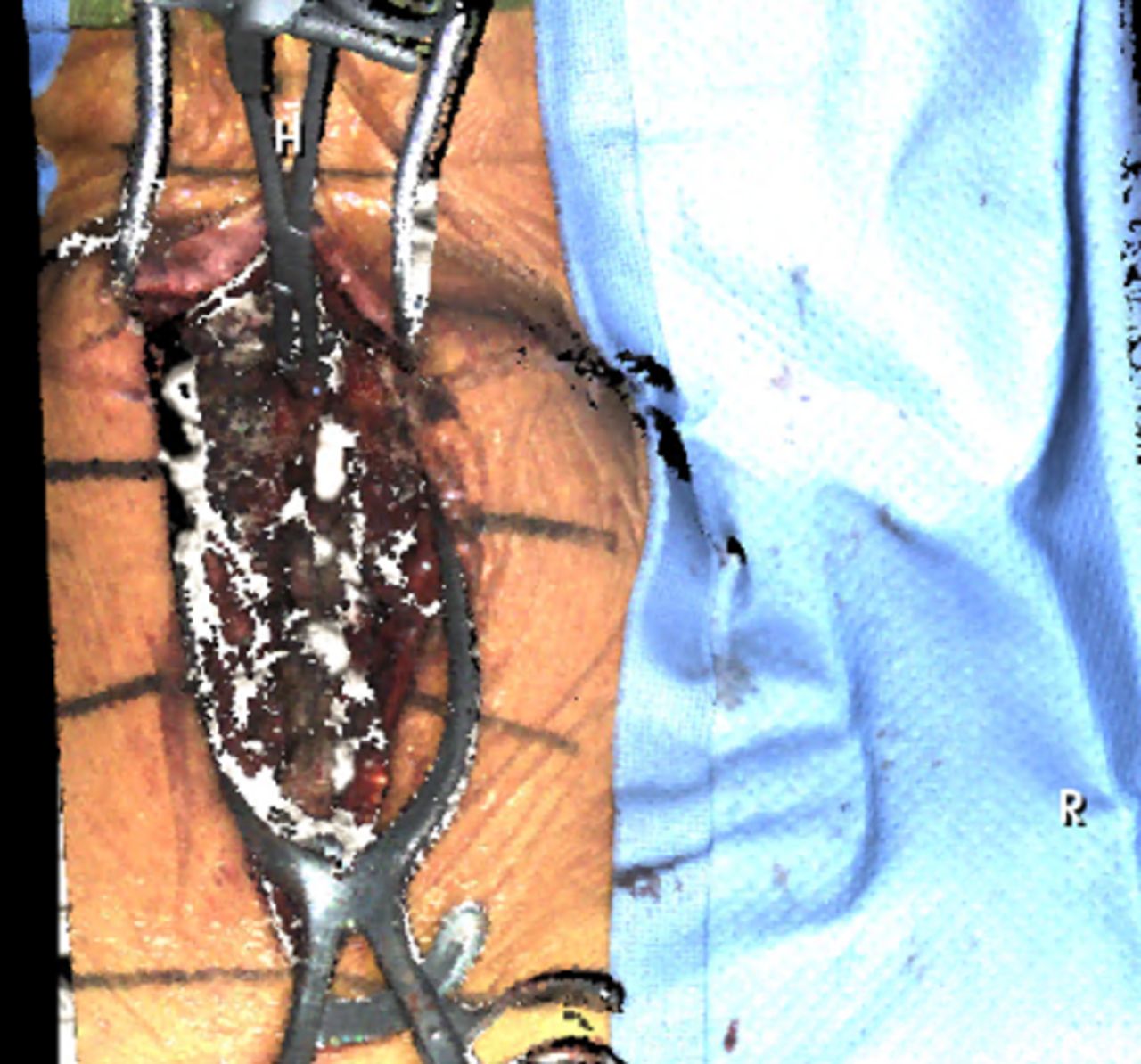
Structured light image of operative site of case 2 by the 7D Surgical System. H = head, R = right.

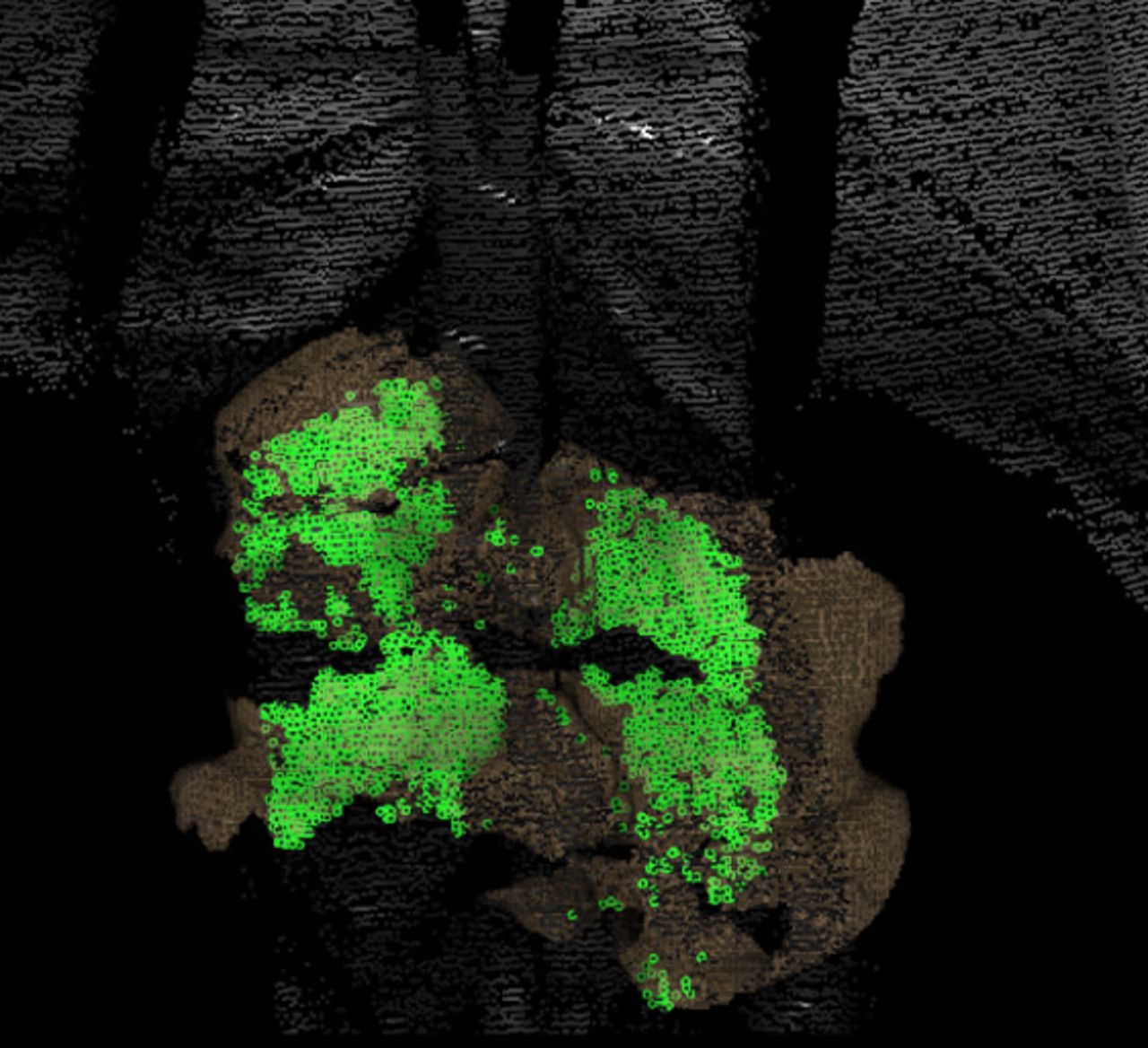
A total of 2751 points matched to preoperative computed tomography image at C3-C4 in case 2.

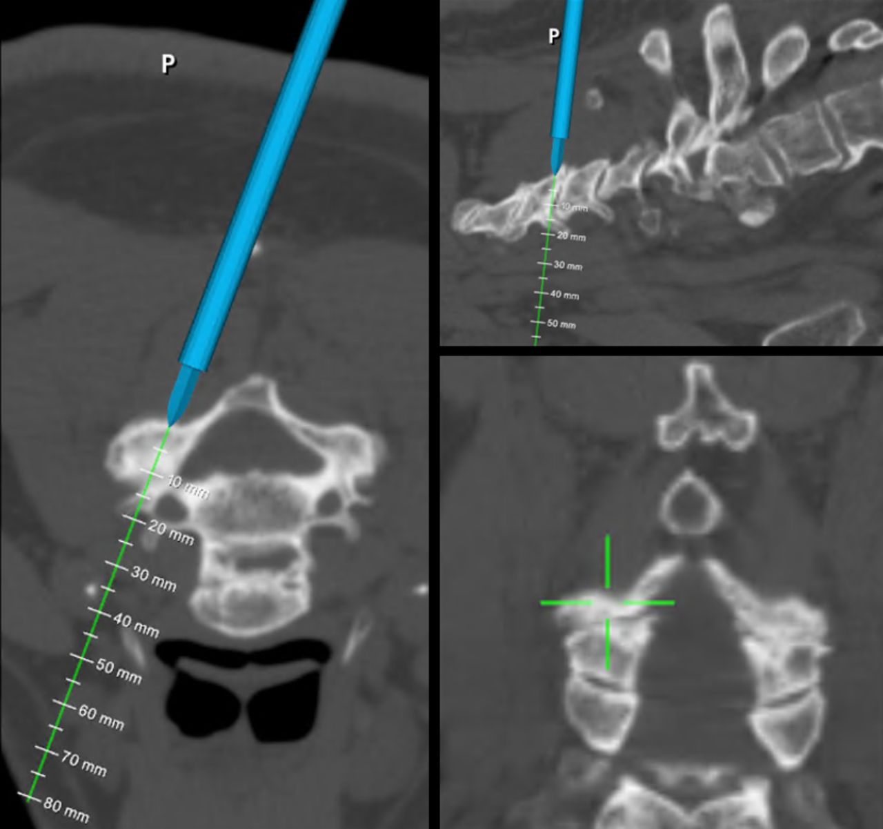
Intraoperative navigation of lateral mass screws in case 2 (P = posterior).

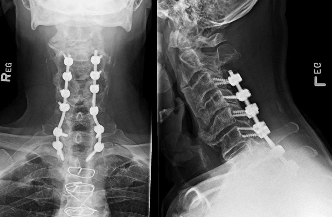
Postoperative anteroposterior and lateral radiographs of the patient in case 2.
Illustrative Case 3
Case 3 is a 24-year-old woman with a painful progressive apex right scoliosis of 75° T6-L1 with the apex at T8-T9. Pedicles on the left of the apex were markedly hypoplastic, as clearly evident on the CT image. She underwent instrumented arthrodesis T4-L2 with 7D navigation. Preoperative radiographs are shown in Figure 12, an intraoperative image in Figure 13, point matching in Figure 14, and intraoperative navigation in Figure 15. Surgical field set-up is shown in Figure 16. Figure 17 comprises the anteroposterior and lateral postoperative radiographs.

Preoperative radiographs consisting of unbend right and left anteroposterior and neutral lateral radiographs of case 3.

Structured light image of operative site by 7-dimensional for case 3.

A total of 2073 points matched to the preoperative computed tomography image at T8 for case 3.

Navigation of the right T8 screw in case 3. It is evident from the axial image the left pedicle cannot be safely instrumented. P = posterior; H = head.

View of the operative field and our preferred positioning of the 7D Surgical System machine and monitor. Note that with this system, no imaging equipment comes between surgeon and patient.
Postoperative radiographs of the patient in case 3. Sublaminar bands were placed at the apex of the concavity to aid derotation of the spine, where the pedicle diameter was too small to allow screw placement. L = left, R = right.
Illustrative Case 4
Case 4 is a demonstration that existing instrumentation is not a contraindication to machine vision navigation. In fact, existing spinal instrumentation can be used as a fixed registration point for instrumenting adjacent levels. The patient is a 72-year-old woman who 12 years previously underwent instrumented arthrodesis T10-L5. She presented after a fall with thoracic back pain, lower extremity spasticity, and intermittent urinary incontinence. Imaging demonstrated stenosis at T8-T9 and T9-T10. She underwent decompression of her stenosis with extension of her fusion to T7. Preoperative radiographs are presented in Figure 18 and intraoperative image in Figure 19. Matched points are demonstrated in Figure 20 and intraoperative navigation in Figure 21. Postoperative radiographs are presented in Figure 22.
Preoperative radiographs of the patient in case 4 demonstrating interspace narrowing and junctional kyphosis.

Structured light image of the operative field in case 4. The existing screws at T10 and T11 are visible, as well as the array clamped to T9. H = head, R = right.

Registration matching of 3376 discrete points on the dorsal elements results in dense green image (case 4).

Navigation of T7 screws in case 4. Note existing instrumentation is visible in the image.

Postoperative radiographs of the patient in case 4. Navigated screws T7-T9 connected to existing rods. The patient had rapid resolution of her neurologic symptoms.
OUTCOMES
In this case series of 150 patients, there were no instances of symptomatic screw malposition. Two patients underwent postoperative CT demonstrating all screws appropriately positioned with no evidence of pedicle breach. No patient required reoperation or repeat hospital admission.
The total operative time for my most recent 5 thoracolumbar deformity cases was 20% lower with use of machine vision than C-arm (4.2 vs 5.3 hours from incision to closure). The average time for flash registration and insertion of bilateral screws at each level was 5 minutes 25 seconds, whereas the average time utilizing C-arm was 7 minutes 30 seconds after the C-arm position was optimized.
DISCUSSION
Visible light navigation is ideally suited to the practice of open complex spinal surgery. The system is most useful where it is most needed, the cervical and thoracic spine where visualization by the 7D is enhanced by better exposure of the spine. The system not only facilitates screw placement, but it also provides the important real-time feedback that some pedicles are too small or deformed to allow safe screw placement. The exposure required is that of a typical open surgery exposing facets and transverse process; there is no need for aggressive soft tissue/capsule removal.
The learning curve is very short as the controls are intuitive, and the image of the spine provided is a familiar one. In contrast to some other systems, when a navigated instrument is moved the image of the instrument is moved as opposed to the spine moving around the instrument. The vertebra remains the fixed point. By the sixth case with visible light navigation, operative times were shorter than with C-arm.
An additional benefit is the lack of radiation, so the operating room staff does not need to wear lead. As there is no C-arm between the surgeon and the patient, the team can assume a more natural and comfortable stance while performing the operation. Strain on the surgeon and assistant is reduced as there is no need to lean over the C-arm during pedicle instrumentation.
The major limitation to this technology is the need for adequate exposure of vertebrae as in traditional open spine surgery. The system currently cannot currently be used in minimal-incisional surgery. An additional limitation is visualization of the lumbosacral junction in very large or muscular patients. Visualization of the sacrum is often limited to the point where isolated registration of S1 is not possible. This can often be overcome by doing a “block registration” of L5 and S1 together and registering 4 to 6 points on the 2 segments.
CONCLUSION
Visible light navigation of pedicle screw placement has proven safe and effective in the practice of complex open spine surgery. In this cohort of 150 consecutive cases, there were no symptomatic cases of pedicle breach. Operative time is improved with visible light navigation vs C-arm, and the lack of intraoperative radiation is an added benefit.
Footnotes
Funding The author received no financial support for the research, authorship, and/or publication of this article.
Declaration of Conflicting Interests The author is a consultant for 7D Surgical and hosts visiting surgeons.
- This manuscript is generously published free of charge by ISASS, the International Society for the Advancement of Spine Surgery. Copyright © 2022 ISASS. To see more or order reprints or permissions, see http://ijssurgery.com.
In this issue


Jump to section
Related Articles
Cited By...
- No citing articles found.