
Main menu

  • Home
  • Content
    • Current Issue
    • Advance Online Publication
    • Archive
  • About Us
    • About ISASS
    • About the Journal
    • Author Instructions
    • Editorial Board
    • Reviewer Guidelines & Publication Criteria
  • More
    • Advertise
    • Subscribe
    • Alerts
    • Feedback
  • Join Us
  • Reprints & Permissions
  • Sponsored Content
  • Other Publications
    • ijss

User menu

  • My alerts

Search

  • Advanced search
International Journal of Spine Surgery
  • My alerts
International Journal of Spine Surgery

Advanced Search

  • Home
  • Content
    • Current Issue
    • Advance Online Publication
    • Archive
  • About Us
    • About ISASS
    • About the Journal
    • Author Instructions
    • Editorial Board
    • Reviewer Guidelines & Publication Criteria
  • More
    • Advertise
    • Subscribe
    • Alerts
    • Feedback
  • Join Us
  • Reprints & Permissions
  • Sponsored Content
  • Follow ijss on Twitter
  • Visit ijss on Facebook
Research ArticleFull Length Article
Open Access

Biomechanics of a Fixed–Center of Rotation Cervical Intervertebral Disc Prosthesis

Neil R. Crawford, Seungwon Baek, Anna G.U. Sawa, Sam Safavi-Abbasi, Volker K.H. Sonntag and Neil Duggal
International Journal of Spine Surgery January 2012, 6 34-42; DOI: https://doi.org/10.1016/j.ijsp.2011.10.003
Neil R. Crawford
aSpinal Biomechanics Laboratory, Barrow Neurological Institute, Phoenix, AZ
PhD
  • Find this author on Google Scholar
  • Find this author on PubMed
  • Search for this author on this site
  • For correspondence: neil.crawford@chw.edu
Seungwon Baek
aSpinal Biomechanics Laboratory, Barrow Neurological Institute, Phoenix, AZ
MS
  • Find this author on Google Scholar
  • Find this author on PubMed
  • Search for this author on this site
Anna G.U. Sawa
aSpinal Biomechanics Laboratory, Barrow Neurological Institute, Phoenix, AZ
MS
  • Find this author on Google Scholar
  • Find this author on PubMed
  • Search for this author on this site
Sam Safavi-Abbasi
bDepartment of Neurosurgery, College of Medicine, University of Oklahoma, Oklahoma City, OK
MD
  • Find this author on Google Scholar
  • Find this author on PubMed
  • Search for this author on this site
Volker K.H. Sonntag
aSpinal Biomechanics Laboratory, Barrow Neurological Institute, Phoenix, AZ
MD
  • Find this author on Google Scholar
  • Find this author on PubMed
  • Search for this author on this site
Neil Duggal
cDepartment of Neurological Surgery, London Health Sciences Centre, London, Ontario, Canada
MD
  • Find this author on Google Scholar
  • Find this author on PubMed
  • Search for this author on this site
  • Article
  • Figures & Data
  • Info & Metrics
  • PDF
Loading

Article Figures & Data

Figures

  • Tables
  • Fig. 1
    • Download figure
    • Open in new tab
    • Download powerpoint
    Fig. 1

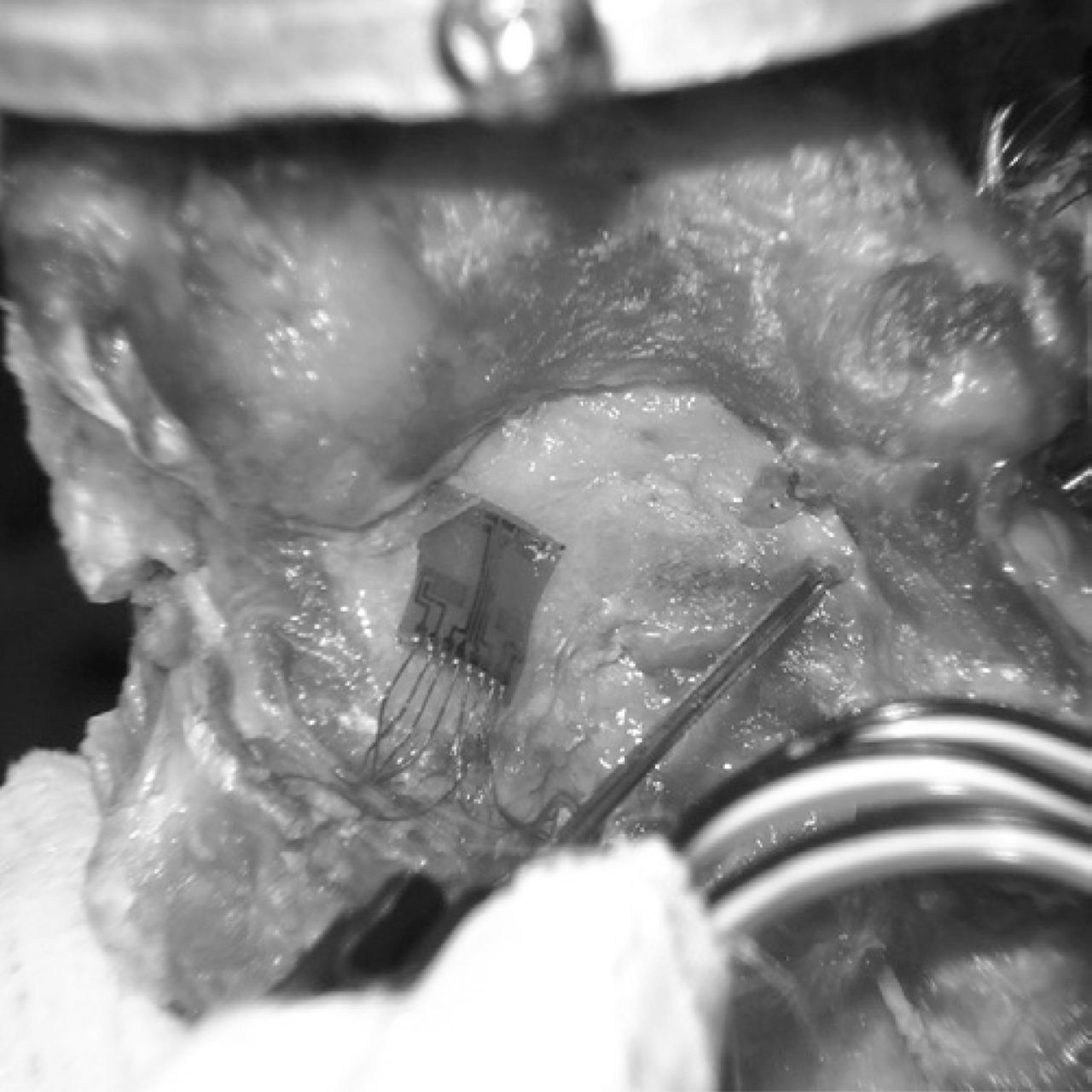
    Posterior photo of specimen showing placement of strain gauge pads on lamina near facet joint. The pads contained 4 uniaxial gauges oriented parallel. The pads were aligned with gauge axes approximately parallel to the predicted primary direction of loading when the facets were compressed.

  • Fig. 2
    • Download figure
    • Open in new tab
    • Download powerpoint
    Fig. 2

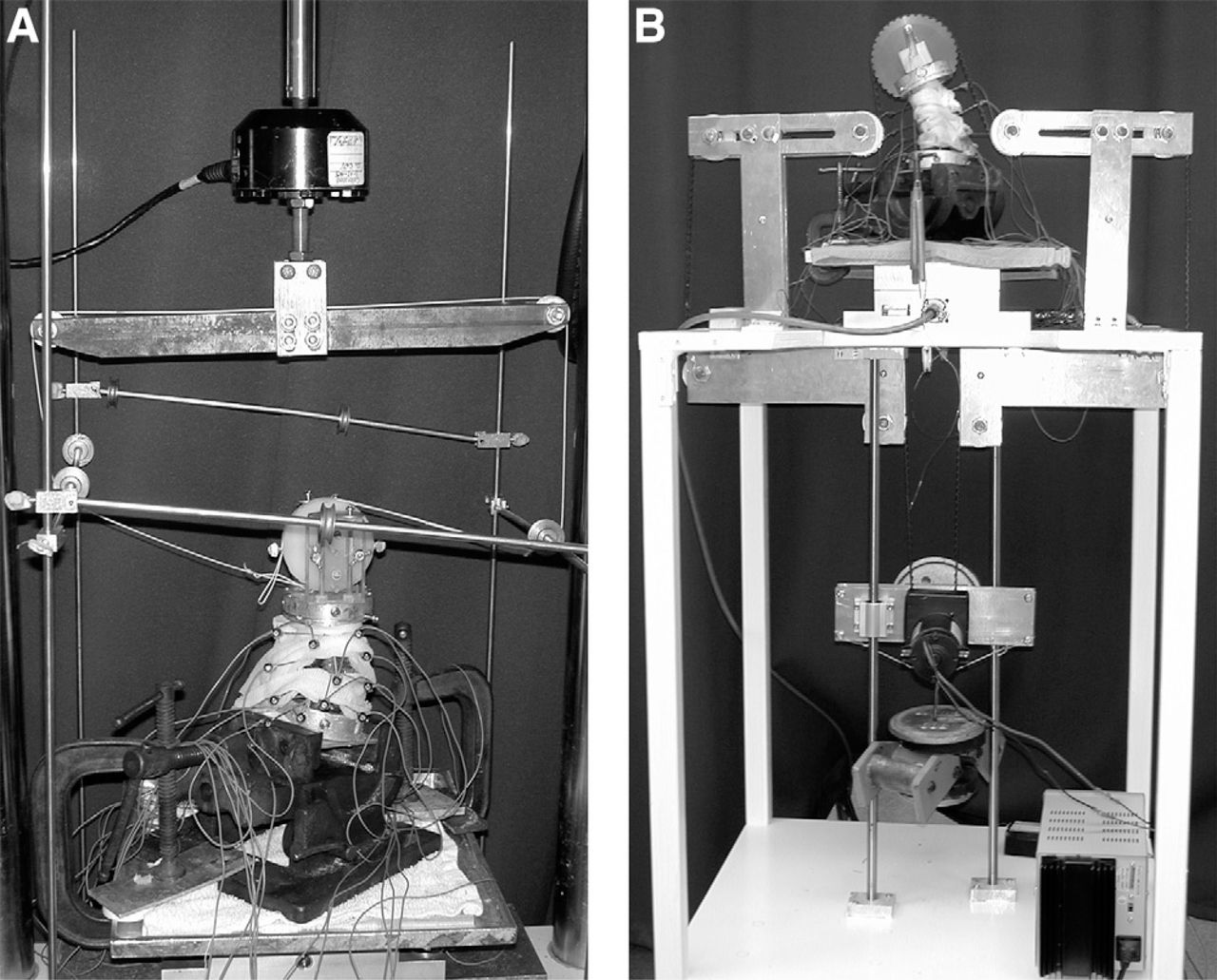
    Specimen loading configurations. (A) Photo from a right-side perspective of a pure moment flexibility test. Strings and pulleys in conjunction with a standard servohydraulic test frame were used to induce flexion (shown), extension, axial rotation, and lateral bending. (B) Photo from a left-side perspective of a flexion-compression test. An electric motor connected to the upper fixture with a heavy-duty belt induced flexion or extension. Weights hung from the motor applied a constant compressive follower load of 70 N. Because of the orientation of the pulleys, the direction of the follower load stayed aligned with the axis of the specimen throughout movement.

  • Fig. 3
    • Download figure
    • Open in new tab
    • Download powerpoint
    Fig. 3

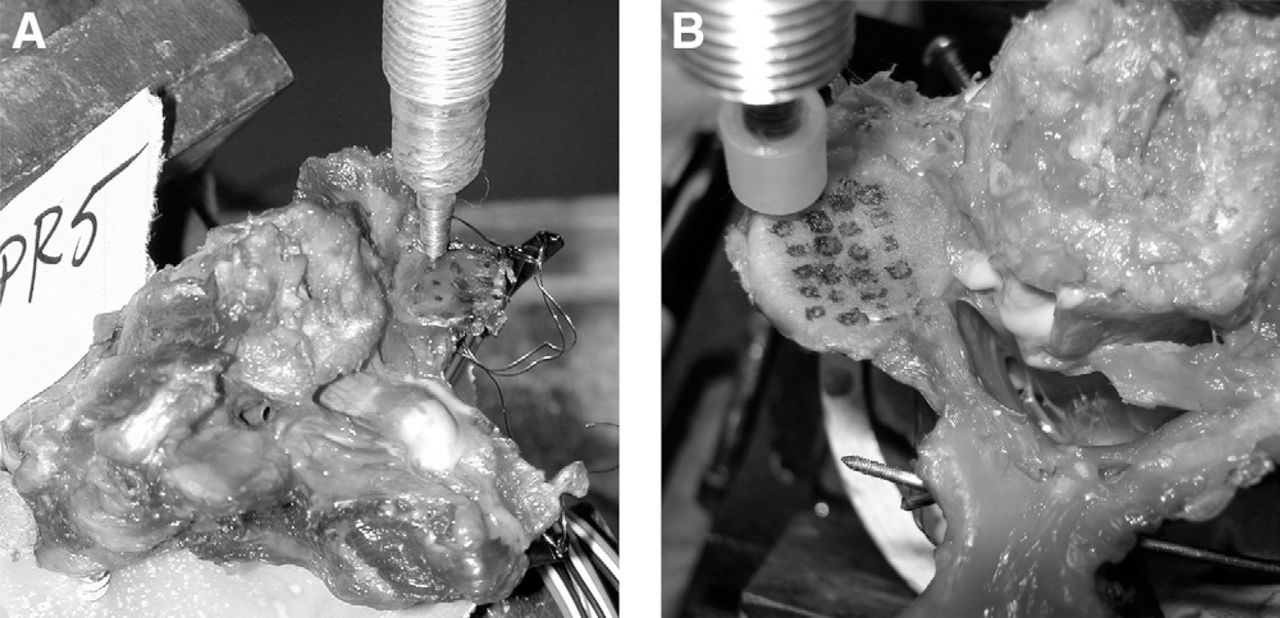
    Calibration of strain gauges required the specimen to be disarticulated after completion of testing. Then, test loads were applied with the MTS piston fitted with a plunger. Loads were applied to a series of points (shown marked with permanent ink) while output from each strain gauge was recorded. A neural network model used these test loads to establish the relationship between strain gauges and facet load. (A) In the first 6 specimens, a metal plunger with a small tip was used. (B) In the last 4 specimens, a rounded plastic plunger was used, which provided a surface mimicking the opposing facet better than the metal plunger.

  • Fig. 4
    • Download figure
    • Open in new tab
    • Download powerpoint
    Fig. 4

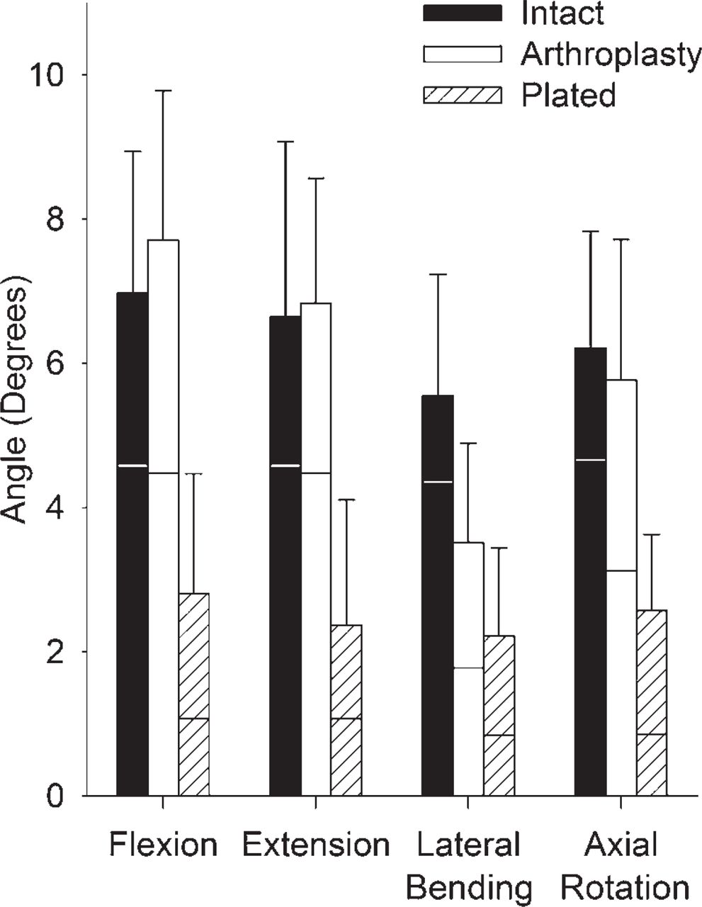
    Mean angular motion in each condition studied. Full bars represent ROM; the portion below the horizontal line represents LZ, and the portion above the horizontal line represents SZ. Error bars show standard deviation of ROM.

  • Fig. 5
    • Download figure
    • Open in new tab
    • Download powerpoint
    Fig. 5

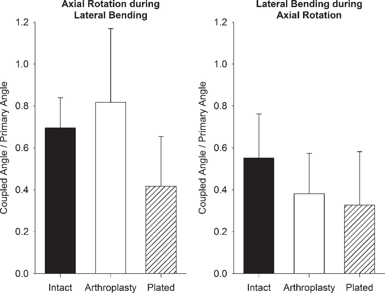
    Angular coupled rotation per degree of primary rotation at C4-5 showing coupling pattern between lateral bending and axial rotation. Error bars show standard deviation.

  • Fig. 6
    • Download figure
    • Open in new tab
    • Download powerpoint
    Fig. 6

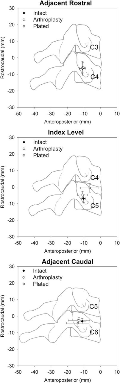
    Mean location of axis of rotation in sagittal plane during flexion to extension at index (C4-5) and adjacent (C3-4 and C5-6) levels. Error bars show standard deviation.

  • Fig. 7
    • Download figure
    • Open in new tab
    • Download powerpoint
    Fig. 7

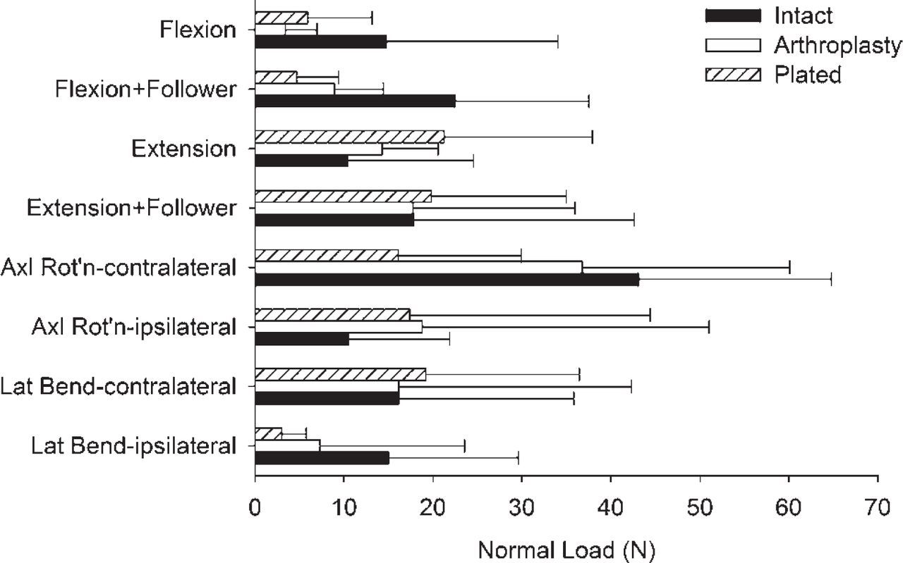
    Mean facet loads during different conditions of specimen loading. Facet loads during flexion and extension are averages of right and left sides. Error bars show standard deviation. (Axl Rot'n, axial rotation; Lat Bend, lateral bending.)

Tables

  • Figures
    • View popup
    Table 1

    Mean angular ROM, LZ, and SZ

    Parameter and loading modeNormal (mean ± SD) (°)Arthroplasty (mean ± SD) (°)Plated (mean ± SD) (°)
    ROM
     Flexion7.0 ± 1.6*7.8 ± 1.9*3.2 ± 2.3
     Extension6.9 ± 1.9*6.7 ± 1.9*2.9 ± 2.0
     Lateral bending5.4 ± 1.6*3.8 ± 1.3*†2.6 ± 1.5
     Axial rotation6.1 ± 1.4*5.7 ± 1.6*3.0 ± 1.4
    LZ
     Flexion-extension9.5 ± 2.8*9.7 ± 3.6*2.9 ± 3.2
     Lateral bending8.4 ± 2.9*4.2 ± 2.0†2.3 ± 2.1
     Axial rotation9.1 ± 2.2*6.1 ± 2.4*†2.5 ± 2.3
    SZ
     Flexion2.2 ± 0.52.9 ± 0.9*1.7 ± 0.9
     Extension2.2 ± 0.61.9 ± 0.91.4 ± 0.6
     Lateral bending1.2 ± 0.21.7 ± 0.5†1.4 ± 0.6
     Axial rotation1.5 ± 0.42.6 ± 0.8*†1.7 ± 0.4
    • ↵* Significantly different from plated.

    • ↵† Significantly different than intact.

    • View popup
    Table 2

    Summary of alterations relative to intact condition observed for arthroplasty-implanted and plated conditions

    ParameterArthroplastyPlated
    ROM
     FlexionNo changeSubstantial decrease
     ExtensionNo changeSubstantial decrease
     Lateral bendingMild decreaseSubstantial decrease
     Axial rotationNo changeSubstantial decrease
    LZ
     Flexion-extensionNo changeSubstantial decrease
     Lateral bendingMild decreaseSubstantial decrease
     Axial rotationMild decreaseSubstantial decrease
    SZ
     FlexionNo changeNo change
     ExtensionNo changeNo change
     Lateral bendingMild increaseNo change
     Axial rotationMild increaseNo change
    Coupled axial rotation during lateral bendingNo changeSubstantial decrease
    Coupled lateral bending during axial rotationSubstantial decreaseSubstantial decrease
    Anteroposterior position of axis of rotationNo changeSubstantial increase
    Rostrocaudal position of axis of rotationMild increaseSubstantial increase
    Facet load during flexionMild decreaseMild decrease
    Facet load during other loadingNo changeNo change
PreviousNext
Back to top

In this issue

International Journal of Spine Surgery
Vol. 6
1 Jan 2012
  • Table of Contents
  • Index by author

Print
Download PDF
Article Alerts
Sign In to Email Alerts with your Email Address
Email Article

Thank you for your interest in spreading the word on International Journal of Spine Surgery.

NOTE: We only request your email address so that the person you are recommending the page to knows that you wanted them to see it, and that it is not junk mail. We do not capture any email address.

Enter multiple addresses on separate lines or separate them with commas.
Biomechanics of a Fixed–Center of Rotation Cervical Intervertebral Disc Prosthesis
(Your Name) has sent you a message from International Journal of Spine Surgery
(Your Name) thought you would like to see the International Journal of Spine Surgery web site.
CAPTCHA
This question is for testing whether or not you are a human visitor and to prevent automated spam submissions.
Citation Tools
Biomechanics of a Fixed–Center of Rotation Cervical Intervertebral Disc Prosthesis
Neil R. Crawford, Seungwon Baek, Anna G.U. Sawa, Sam Safavi-Abbasi, Volker K.H. Sonntag, Neil Duggal
International Journal of Spine Surgery Jan 2012, 6 34-42; DOI: 10.1016/j.ijsp.2011.10.003

Citation Manager Formats

  • BibTeX
  • Bookends
  • EasyBib
  • EndNote (tagged)
  • EndNote 8 (xml)
  • Medlars
  • Mendeley
  • Papers
  • RefWorks Tagged
  • Ref Manager
  • RIS
  • Zotero
Share
Biomechanics of a Fixed–Center of Rotation Cervical Intervertebral Disc Prosthesis
Neil R. Crawford, Seungwon Baek, Anna G.U. Sawa, Sam Safavi-Abbasi, Volker K.H. Sonntag, Neil Duggal
International Journal of Spine Surgery Jan 2012, 6 34-42; DOI: 10.1016/j.ijsp.2011.10.003
Twitter logo Facebook logo Mendeley logo
  • Tweet Widget
  • Facebook Like
  • Google Plus One

Jump to section

  • Article
    • Abstract
    • Methods
    • Results
    • Discussion
    • Conclusions
    • References
  • Figures & Data
  • Info & Metrics
  • PDF

Related Articles

  • No related articles found.
  • Google Scholar

Cited By...

  • In Vitro Biomechanics of Human Cadaveric Cervical Spines With Mature Fusion
  • Google Scholar

More in this TOC Section

  • Transforaminal lumbar interbody fusion rates in patients using a novel titanium implant and demineralized cancellous allograft bone sponge
  • Kyphoplasty versus vertebroplasty for painful osteoporotic vertebral compression fractures—which one is better? A systematic review and meta-analysis
  • Overtightening of halo pins resulting in intracranial penetration, pneumocephalus, and epileptic seizure
Show more Full Length Article

Similar Articles

Keywords

  • artificial disc
  • Biomechanics
  • kinematics

Content

  • Current Issue
  • Latest Content
  • Archive

More Information

  • About IJSS
  • About ISASS
  • Privacy Policy

More

  • Subscribe
  • Alerts
  • Feedback

Other Services

  • Author Instructions
  • Join ISASS
  • Reprints & Permissions

© 2025 International Journal of Spine Surgery

International Journal of Spine Surgery Online ISSN: 2211-4599

Powered by HighWire