ABSTRACT
Introduction This study develops and validates an accurate, computationally efficient, 3-dimensional finite element model (FEM) of the human lumbar spine. Advantages of this simplified model are shown by its application to a disc degeneration study that we demonstrate is completed in one-sixth the time required when using more complicated computed tomography (CT) scan–based models.
Methods An osseoligamentous FEM of the L1–L5 spine is developed using simple shapes based on average anatomical dimensions of key features of the spine rather than CT scan images. Pure moments of 7.5 Nm and a compressive follower load of 1000 N are individually applied to the L1 vertebra. Validation is achieved by comparing rotations and intradiscal pressures to other widely accepted FEMs and in vitro studies. Then degenerative disc properties are modeled and rotations calculated. Required computation times are compared between the model presented in this paper and other models developed using CT scans.
Results For the validation study, parameter values for a healthy spine were used with the loading conditions described above. Total L1–L5 rotations for flexion, extension, lateral bending, and axial rotation under pure moment loading were calculated as 20.3°, 10.7°, 19.7°, and 10.3°, respectively, and under a compressive follower load, maximum intradiscal pressures were calculated as 0.68 MPa. These values compare favorably with the data used for validation. When studying the effects of disc degeneration, the affected segment is shown to experience decreases in rotations during flexion, extension, and lateral bending (24%–56%), while rotations are shown to increase during axial rotation (14%–40%). Adjacent levels realize relatively minor changes in rotation (1%–6%). This parametric study required 17.5 hours of computation time compared to more than 4 days required if utilizing typical published CT scan–based models, illustrating one of the primary advantages of the model presented in this article.
Conclusions The FEM presented in this article produces a biomechanical response comparable to widely accepted, complex, CT scan–based models and in vitro studies while requiring much shorter computation times. This makes the model ideal for conducting parametric studies of spinal pathologies and spinal correction techniques.
INTRODUCTION
Low back pain is a prevalent health issue with a lifetime incidence rate of 58%–84%.1 Economic implications are significant, as low back pain is a leading cause of workplace absence around the world.2 A wide variety of conditions can cause low back pain, and considerable research has been performed over the past several decades to determine treatment methods with the highest likelihood of success. In recent years, the finite element method (FEM) has emerged as an efficient and useful tool to aid in the research of conditions related to the lower back and spine.
The lumbar region of the human spine is the most inferior region of the spinal column and consists of the bottom 5 vertebrae L1–L5. Due to its location, the lumbar spine experiences significant mechanical loads caused by the weight of the torso and movements such as bending and lifting.3 Existing research on the lumbar spine utilizing finite element analysis (FEA) focuses on many areas ranging from disorders such as scoliosis, disc degeneration, and osteoporosis4–6 to spinal correction techniques such as spinal fusion, disc replacement, and decompression.7–9 Among the earliest of such studies was a paper written by Belytschko et al10 in 1974 investigating stress analysis of an intervertebral disc (IVD) using FEA.
Beginning in the 1990s and early 2000s, there was a marked increase in the amount of research being performed on FEA of the spine. This can be attributed, at least in part, to the advancement in computing capabilities and the emergence of commercial FEA computer programs. Today, highly detailed, 3-dimensional, nonlinear FEMs of the lumbar spine based on computed tomography (CT) scans are commonly used to investigate areas of interest.
Interbody spacers, or cages, are the subject of much research using FEA. Material selection and porosity of cages and their effect on stresses and range of motion (ROM) have been investigated in detail.11–13 Surgical approach and placement of interbody cages is another point of consideration, including posterior lumbar interbody fusion, transforaminal lumbar interbody fusion, and posterolateral lumbar interbody fusion, among others.14–16 Scoliosis and brace design, vibration, and posterior instrumentation associated with spinal fusion surgery have all been studied in great detail.17–20
In the majority of cases, FEA research of the lumbar spine is performed using CT scan–based models. Often, this requires highly refined meshes with many nodes and elements to properly capture the detail that a CT scan provides. With an increase in nodes and elements comes an increase in the required computing power. Each additional degree of freedom in an FEM increases the size of the stiffness matrix, thereby increasing the number of coupled algebraic equations that must be solved simultaneously. This imposes added burden on computational resources and can create impractically lengthy computation times when considering parametric studies involving many combinations of inputs. As an alternative approach, this paper presents a computationally efficient FEM (referred to herein as the computationally efficient model [CEM]) of the lumbar spine that uses generalized 3-dimensional shapes to represent the individual components of the spine. These shapes will be designed using average anatomical dimensions of key spinal landmarks,21 but the model will not include subject-specific surface contours of each part of the spine. To achieve results with accuracy comparable to CT scan–based models, the level of mesh refinement required by the CEM will be shown to be significantly lower. This will drastically reduce computation times, and we will show that the accuracy of the biomechanical response of the CEM presented is preserved while requiring significantly less computation time than CT scan–based models. The benefits of this CEM will be demonstrated by its application to disc degeneration and its effect on the ROMs in the degenerated and adjacent segments.
METHODS
Healthy Model
A healthy, osseoligamentous FEM of the lumbar spine from L1–L5 is developed using average anatomical dimensions of key landmarks of the human spine21 (Figure 1). The individual 3-dimensional computer-aided design (CAD) files are created using Solidworks 2012 (Dassault Systems SA, Waltham, Massachusetts). The CAD files are then imported into ANSYS 14.5 (ANSYS, Canonsburg, Pennsylvania), a commercially available FEA software package, for analysis. The cortical and cancellous bones of the vertebrae are modeled as elliptical cylinders using average dimensions of upper and lower end plate width and depth and vertebral body height. The cortical bone thickness is set as 1 mm and meshed with shell elements.22 The posterior bones are modeled using average dimensions of transverse process length, spinous process length, spinous process angle, and spinal canal width and depth. The IVD is composed of an inner and an outer portion. The inner portion is the nucleus pulposus (NP) and is surrounded by the annulus fibrosus (AF). The NP and AF are modeled as concentric elliptical cylinders using average dimensions of IVD height, width, and depth. On average, approximately 90% of the normal curvature in the lumbar spine is created by contributions from the IVDs.23 Therefore, the cylinders representing the AF and NP are wedge-shaped in order to achieve the appropriate lumbar lordosis.21 The NP is treated as a nearly incompressible substance with a cross-sectional area totaling 40% of the entire disc area.24 The AF is composed of fibrous tissue in concentric bands. Each band is oriented with its fibers alternating ±30° to the disc plane.3 The AF fibers are active in tension only. The 7 major ligaments of the spine are included in this model as tension-only spring elements with nonlinear loading and unloading characteristics. Facet joints are modeled as frictionless contact pairs with an average initial gap25 of 0.5 mm. Table 1 provides a summary of the bone and disc material properties used in this analysis. Table 2 provides description of the nonlinear loading and unloading characteristics26 of the spinal ligaments. The numerical values of the key spinal anatomical dimensions21 used in this study are presented in Table 3.
Finite element model of the lumbar spine used in this article.
Material properties used in the finite element model of the lumbar spine.
Nonlinear loading and unloading characteristics of the lumbar spinal ligaments.a
Geometric dimensions21 used for finite element modeling of the spine.
Degenerated Model
In studying the effects of disc degeneration on ROMs in the degenerated and adjacent segments, each IVD within the healthy model described earlier is separately modified to reflect a disc experiencing moderate levels of degeneration. Taking guidance from Homminga et al27 and Kumaresan et al,28 moderate degeneration includes changes in the NP due to dehydration and changes in the AF and AF fibers. Severe degeneration, including changes in disc height,28 is not considered in this article. Parameters relating to the NP and AF that are modified include the Young modulus and Poisson ratio. Material properties27 for the moderately degenerated discs used in our study are listed in Table 4.
Material properties for moderately degenerated intervertebral discs.27
Boundary and Loading Conditions
For the validation of the healthy lumbar spine CEM, the inferior face of the L5 vertebra is fixed against all 6 degrees of freedom (translation and rotation). Both the load-deflection relationship and intradiscal pressure will be used to validate this model. First, a pure moment of 7.5 Nm is applied to the superior face of the L1 vertebra in the 3 standardized loading directions for spinal testing: flexion-extension, lateral bending, and axial rotation.29 The load-deflection relationship in each direction is recorded (moment versus angular displacement). Second, a compressive load of 1000 N is applied to the superior face of the L1 vertebra. The follower load technique30 is used to reduce the presence of artifact bending moments during application of the load. The maximum von Mises stress in the L4–L5 disc is recorded. These loading and boundary conditions are consistent with those used in the study by Dreischarf et al,31 the results of which will be used for comparison and validation of the CEM.
Boundary conditions used for the degenerated CEM are the same as those used for the healthy CEM, as described earlier. In studying the effects of disc degeneration, each disc will be modified separately to reflect moderate degeneration. In each of these cases, a pure moment of 7.5 Nm is applied to the superior face of the L1 vertebra in flexion-extension, lateral bending, and axial rotation. Maximum ROMs are recorded for each motion segment in the degenerated CEM, and comparisons are made to the healthy spine CEM ROMs.
RESULTS
Healthy Model (Validation Study)
The results presented in this section were used to validate our CEM, as will be discussed briefly in this section and in greater detail during the discussion of results. The nonlinear load-deflection relationship for the CEM of the healthy spine when subjected to a pure moment of 7.5 Nm is presented in Figure 2 (the motions of flexion, extension, lateral bending, and axial rotation are presented). The total L1–L5 rotations for flexion, extension, lateral bending, and axial rotation are 20.3°, 10.7°, 19.7°, and 10.3°, respectively. The maximum von Mises stress in the L4–L5 disc as a function of applied compression force is presented in Figure 3. Under a compression load of 1000 N, the maximum von Mises stress is 0.68 MPa. The maximum total L1–L5 rotations under a pure moment of 7.5 Nm for the motions of flexion-extension, lateral bending (left and right), and axial rotation (clockwise and counterclockwise) are provided in Figure 4. The total rotations in flexion-extension, lateral bending (left and right), and axial rotation (clockwise and counterclockwise) are 31.0°, 39.3°, and 20.7°, respectively. Note that in Figures 2 through 4, our results are compared with other well-established and previously published FEMs and in vitro data sets for validation purposes. This validation will be detailed in the Discussion section.
Validation of computationally efficient model healthy spine L1–L5 load-deflection relationship under pure moment of 7.5 Nm.
Validation of computationally efficient model healthy spine L4–L5 intradiscal pressure under compression load of 1000 N.
Validation of computationally efficient model healthy spine total L1–L5 range of motion under pure moment of 7.5 Nm.
Degenerated Model
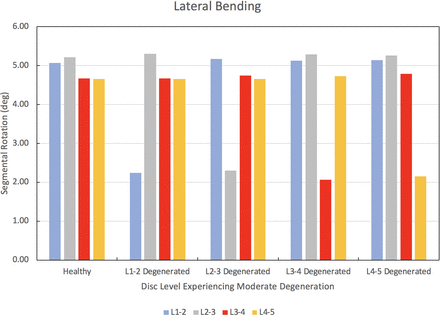
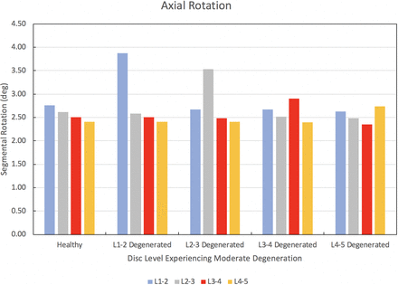
The results of the degenerated disc model are compared to the results of the healthy model developed herein. Each disc in the healthy spine CEM discussed earlier is separately modified using degenerated disc properties. Under a pure moment of 7.5 Nm in flexion, extension, lateral bending, and axial rotation, the degenerated CEM ROM results are compared to the healthy spine results. Figure 5 provides this comparison for the flexion loading condition. Similarly, Figures 6 through 8 provide the comparison for the extension, lateral bending, and axial rotation loading conditions, respectively. In flexion, the maximum percent decrease in segmental ROM is 43% and occurs in the L2–L3 disc when the L2–L3 disc is moderately degenerated. The maximum increase in ROM during flexion is 4% and occurs in the L2–L3 disc when the L1–L2 disc is moderately degenerated. In extension, the maximum percent decrease in segmental ROM is 29% and occurs in the L3–L4 disc when the L3–L4 disc is moderately degenerated. The maximum increase in ROM during extension is 3% and occurs in the L2–L3 disc when the L1–L2 disc is moderately degenerated. In lateral bending, the maximum percent decrease in segmental ROM is 56% and occurs in the L1–L2 disc when the L1–L2 disc is moderately degenerated. The maximum increase in ROM during lateral bending is 2% and occurs in the L2–L3 disc when the L1–L2 disc is moderately degenerated. In axial rotation, the maximum percent decrease in segmental ROM is 6% and occurs in the L3–L4 disc when the L4–L5 disc is moderately degenerated. The maximum increase in ROM during axial rotation is 40% and occurs in the L1–L2 disc when the L1–L2 disc is moderately degenerated.
Change in segmental range of motion when comparing a degenerated disc spine computationally efficient model (CEM) to a healthy spine CEM under a pure moment of 7.5 Nm in flexion.
Change in segmental range of motion when comparing a degenerated disc spine computationally efficient model (CEM) to a healthy spine CEM under a pure moment of 7.5 Nm in extension.
Change in segmental range of motion when comparing a degenerated disc spine computationally efficient model (CEM) to a healthy spine CEM under a pure moment of 7.5 Nm in lateral bending.
Change in segmental range of motion when comparing a degenerated disc spine computationally efficient model (CEM) to a healthy spine CEM under a pure moment of 7.5 Nm in axial rotation.
DISCUSSION
The computationally efficient FEM (CEM) presented in this article is developed and validated for use in future research endeavors. Composed of simple geometric shapes without consideration of the detailed surface contour and intricacies that accompany a CT scan–based FEM, we show that the CEM takes only a few minutes to execute. The work by Dreischarf et al31 is chosen for validation because it subjected 8 previously validated and widely accepted lumbar spine FEMs to the same loading conditions as the present work. In that study, the 8 FEMs were compared to 3 different in vitro data sets. Therefore, the present study is validated by comparison to 8 well-established FEMs and 3 in vitro data sets. We note here that for the validation efforts of the CEM presented in this article, we consider intradiscal pressure in addition to using the load-deflection relationship and total ROM in 3 directions of loading, which is in contrast to many existing studies that ignore intradiscal pressure32,33 when validating their respective lumbar spine FEMs. A detailed discussion of results of our validation studies is presented below.
From Figure 2, a pure moment of 7.5 Nm produces total rotations for flexion, extension, lateral bending, and axial rotation within the range of rotations produced by the 8 well-established FEMs from Dreischarf et al.31 Rotations in flexion, extension, and lateral bending are within the range of rotations produced by the 3 in vitro data sets. In axial rotation, the total L1–L5 angular displacement is within 0.09° of the 3 in vitro studies. Under a compressive follower load of 1000 N, the CEM L4–L5 intradiscal pressure is within the range of pressures produced by the 8 well-established FEMs and the 3 in vitro studies. The total angular displacement produced by the present model under a 7.5-Nm moment for flexion-extension, lateral bending (left and right), and axial rotation (clockwise and counterclockwise) is within the upper and lower bound range of values predicted by the 8 well-established FEMs (Figure 4). Compared to the 3 in vitro studies, the flexion-extension and lateral bending (left and right) movements agree favorably. The ROM in axial rotation (clockwise and counterclockwise) is within 1.8° of the upper bound value produced by the 3 in vitro studies. As our results show, the biomechanical response of the CEM presented herein agrees with several relevant in vitro and FEM studies found in the literature, thereby establishing the validation of our present CEM.
We now discuss the results of our disc degeneration study. In the case of disc degeneration, ROMs are shown to decrease in the degenerated disc for flexion (41%–43%), extension (24%–29%), and lateral bending (54%–56%). ROMs increase in the degenerated disc during axial rotation (14%–40%). Figures 5 through 8 provide the results for flexion, extension, lateral bending, and axial rotation when each disc is individually modified using degenerated disc properties. Segmental rotations experience comparatively minor increases in the adjacent discs during flexion, extension, and lateral bending (2%–4%). Segmental rotations realize comparatively minor decreases in the adjacent discs during axial rotation (1%–6%). These results, including the changes in adjacent segment ROMs following degeneration, strongly suggest that degeneration of an IVD may lead to an altered biomechanical response of the spine. Similar studies have been performed on the effects of disc degeneration on the affected and adjacent discs, and the changes in ROM for the affected and adjacent discs in the present study show a similar relationship to other articles on the subject.5,34
Motivation for Developing and Using a Simplified CEM
As noted earlier, the lumbar spine CEM presented herein is composed of simple geometric shapes that lack the detailed surface contour that accompanies a typical CT scan–based FEM. Initially, this method of modeling may raise concerns as to the fidelity of this CEM when compared to highly detailed, patient-specific CT scan–based FEMs. However, this method of modeling can be a powerful and useful complement to CT scan–based FEMs, especially when parametric studies involving many combinations of inputs are desired. Research related to the spine using FEA typically uses a single patient-specific spine model, investigates a problem and/or proposes a novel concept, and presents conclusions that are intended to apply to the population as a whole. The method of modeling presented in this article utilizes average values of key parameters of the spine from a number of patients. Using this method, a spine model can be developed to perform calculations that can be made using average dimensions from a large patient sample size to generate biomechanical results that are representative of the average patient.
Sensitivity studies have been performed using FEA of the lumbar spine to determine which parameters most affect its biomechanical response.35,36 No consideration is given to the patient-specific contour of the vertebral bodies, end plates, annulus, and so on in these studies.35,36 This supports the idea that the intricate details of the surface contour, which are not included in the model presented in this article, do not significantly affect the biomechanics of the spine.
The present study is not the first to utilize simplified modeling techniques to represent portions of the spine. Rather than utilizing solid modeling, as does the present study, some papers have represented the vertebrae and/or IVDs using 2-dimensional beam elements.37–40 And rather than model the IVD using CT scans of actual individuals, other studies have used the boundary of 2 adjacent end plates to extrude a generalized shape of the disc.37,41 This effectively ignores the actual surface and contour of the part, similar to the present study. Other studies have similarly developed 3-dimensional models of individual motion segments of the lumbar spine using various sources of anatomical dimensions rather than using CT scans from a specific subject.41 By contrast, the present work considers the entire lumbar spine L1–L5 instead of just 1 individual motion segment (ie, 2 adjacent vertebrae). These simplified methods of modeling and analysis have proven useful at providing insights and solutions to difficult issues in the field of spine research, as evidenced by their prevalence in the literature, and the CEM developed in this article is a valuable complement to these techniques and is likewise capable of imparting insights and developing solutions to spinal research issues.
Advantages of a Simplified CEM
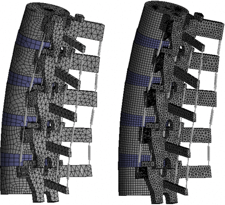
The CEM presented in this article consists of 35 000 nodes and 18 000 elements (approximate). These settings were chosen because our analyses show that the rotational response of the spine does not change significantly if these values are increased. Other studies perform similar mesh convergence tests in order to optimize the efficiency and accuracy of their respective spine models. A review of recent studies shows that on average, lumbar spine FEMs from L1–L5 based on CT scans contain approximately 140 000 nodes.9,11,12,32,43–48 To make a comparison of the computation time required by these models to the time required by the CEM presented in this article, the mesh for the CEM was refined to approximately 140 000 nodes, and a pure moment was applied. When the 140 000-node mesh was used, the model took more than 6 times as long to converge on a solution when compared to the case where 35 000 nodes were used (the standard number of nodes used for the studies presented in this article). A visual comparison between the 2 mesh densities is shown in Figure 9. The model response did not change significantly after refining the mesh. This illustrates that the CEM presented in this article, which is based on simple geometric shapes, does not require a mesh as refined as CT scan–based FEMs and can be executed and converge on a solution in less than one-sixth of the time without sacrificing the accuracy of the results.
Mesh density comparison. Left: computationally efficient model with 35 000 nodes. Right: identical model with 140 000 nodes (the average number of nodes found in CT scan–based FEMs).
The computational efficiency and geometric simplicity of the CEM lends itself to performing parametric studies on various aspects of the spine in a short time frame relative to CT scan–based FEMs. Also, because each part of the CEM is composed of simple geometric shapes based on average key anatomical dimensions, those key dimensions can be parameterized to investigate multiple spine geometries in 1 computer model. Material properties of the disc, ligaments, or any other part of the spine can also be parameterized to investigate multiple scenarios of degenerated discs or other conditions simultaneously. Due to the efficiency of the CEM, these multiple scenarios can be studied without requiring extensive computational resources or run times.
The application of this computationally efficient FEM to disc degeneration, as discussed earlier, required 20 individual analyses considering changes in intradiscal material properties and loading directions. The total time required to execute these analyses was approximately 17.5 hours. If the model mesh were refined to a level comparable to typical CT scan–based FEMs, the total computational time required to execute these analyses would be more than 4 days.
CONCLUSIONS
The present work presents and validates a computationally efficient FEM (CEM) of the lumbar spine based on simplified geometric shapes rather than CT scans and demonstrates that the CEM can accurately predict the biomechanical response of the human spine under standardized loading conditions. The CEM operates efficiently, requiring relatively short run times, and is validated with the same level of accuracy as CT scan–based studies. Geometric and material aspects of the CEM can be parameterized easily to allow for investigation of many combinations of inputs simultaneously. Using the CEM, disc degeneration was studied, including the effects that degeneration has on the ROMs in the affected and adjacent discs. Considerable time savings were realized with this study when using the CEM, and the CEM has been shown to be a useful complement to CT scan–based approaches. Because of its computational efficiency, the CEM presented in this article will be useful for conducting parametric investigations into problems and design issues related to spinal corrective surgery and instrumentation, including spinal fusion surgery and posterior instrumentation techniques.
Footnotes
Disclosures and COI: The authors received no funding for this study and report no conflicts of interest.
- This manuscript is generously published free of charge by ISASS, the International Society for the Advancement of Spine Surgery. Copyright © 2020 ISASS.
