


ABSTRACT
Introduction: The objectives of this paper were to identify and explain specific design factors for lumbar interbody fusion (IBF) devices that can influence bone exchange and stability at the vertebral endplate interface and to provide supporting evidence of these factors through both laboratory and clinical data. The laboratory study (Part 1) compared the pressure profiles and contact areas for a minimally invasive, expandable, and conformable porous mesh (CPM) IBF device and a rigid monolithic lateral PEEK cage (LPC). Furthermore, to demonstrate how these laboratory results translate clinically, a quantitative and qualitative assessment of subject x-rays and computed tomography (CT) scans from a US Food and Drug Administration (FDA) investigational device exemption (IDE) trial of the CPM was performed (Part 2).
Methods: Part 1: Load profile testing. Either CPM or LPC was sandwiched between 2 flat or shaped Grade 15 foam blocks. Each implant type was compressed at a rate of 0.1 mm/s for 3 loads (1100, 2000, or 3000 N). Device and bone graft contact area were analyzed for each test condition, and corresponding load profiles were quantified and mapped using pressure film. Part 2: Radiographic fusion assessment. Two independent radiologists analyzed 12- and 24-month motion studies and CTs for fusion, defined as bridging bone across the intervertebral space. The same CTs were assessed for qualitative biomechanical signs of bone healing.
Results: CPM demonstrated significant direct loading on the bone graft across all tested loading conditions, while the LPC graft registered a negligible amount of pressure at only the extreme load of 3000 N. Contact area was in turn statistically greater (P < .05) for CPM. CPM fusion rates were 97.9% and 99% at 12 and 24 months, respectively. Radiographic signs of bone healing are described in terms of radiating bone struts and regions of greater intensity.
Conclusions: CPM allows for an optimized contact area for bone exchange and graft incorporation. The load profiles demonstrate widespread load sharing across the device. The expandable, compliant, porous mesh provides a unique area for bone exchange, contributing to qualitative biomechanical radiographic evidence of bone healing that ultimately leads to clinically acceptable fusion rates as observed in the FDA IDE trial.
INTRODUCTION
A successful intervertebral fusion requires a biomechanically stable environment that is established through structural support of the unstable motion segment, the integrity of the vertebral endplates and surrounding environment, a favorable biological environment, and direct mechanical loading of the bone graft material to initiate and accelerate mechanotransduction and bone remodeling. Mechanotransduction is the process where cells sense a mechanical stimuli from the extracellular matrix and/or surrounding cells, thus resulting in the cell converting the stimuli into a biological response that will initiate the bone healing and remodeling cascade. The early recruitment of bone to the fusion graft site will promote early anchoring of the graft to the vertebral endplates. The added stability from early attachment at the endplates will result in less micromotion across a fusion site, increasing bone exchange and enhancing the potential for earlier bone remodeling.2–4
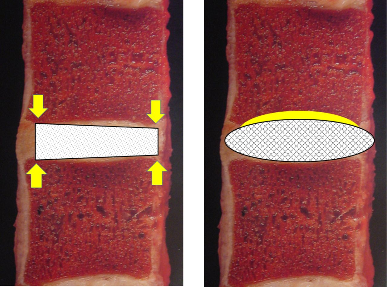
The minimally invasive approach dictates the insertion size of the implant to minimize tissue disruption and thus contributes to greater design challenges when trying to develop a larger expandable footprint in situ that will resist migration while maintaining structural stability.5,6 Graft containment regions of the interbody fusion (IBF) device that allow for multiple planes of entry provide greater area for bone exchange to potentially obtain earlier osseointegration.5–8 Thus, an increase in the direct contact area for the graft material at the endplate interface will increase the chance for homeostatic adaptation by improving stability and reducing the potential for stress risers that may contribute to early implant/host failure (Figure 1).9–11 These responses may be visualized over the course of fusion healing in appropriate imaging (eg, computed tomography [CT] scans).

Contact surface area and conformity illustration of the monolithic PEEK interbody fusion (IBF) device and the conformable porous mesh IBF device. Images adapted from W. Rauschning, MD, Thoracolumbar Spine Anatomy and Pathology, Spine Universe, https://www.spineuniverse.com/professional/pathology/anatomy/thoracolumbar-spine-anatomy-pathology-0.
To illustrate the importance of these design parameters, the objective of this study was 2-fold. In Part 1, we compared vertebral endplate pressure profiles demonstrating the magnitude and extent of direct loading of the fusion grafts under physiological compressive loads along with measurements of the contact areas for each profile that represented the region of direct bone exchange for a minimally invasive, multiplanar, expandable, and conformable porous mesh (CPM) IBF device and a rigid monolithic lateral PEEK cage (LPC). In Part 2, we quantitatively and qualitatively analyzed x-rays and CT scans from a US Food and Drug Administration (FDA) investigational device exemption (IDE) trial of the CPM to determine if the load profiles aligned with the radiographic fusion success seen in the clinical IDE study.
METHODS
Part 1: Load Profile Study
The pressure profiles and contact area for fusion graft loading and bone exchange for a minimally invasive, multiplanar, expandable, and CPM IFB (OptiMesh, Spineology, St Paul, Minnesota) were evaluated. Additionally, similar testing and comparisons were made to a rigid monolithic LPC with a larger footprint than the conformable IBF (Rampart, Spineology). See Figure 2 for representative images of both devices.
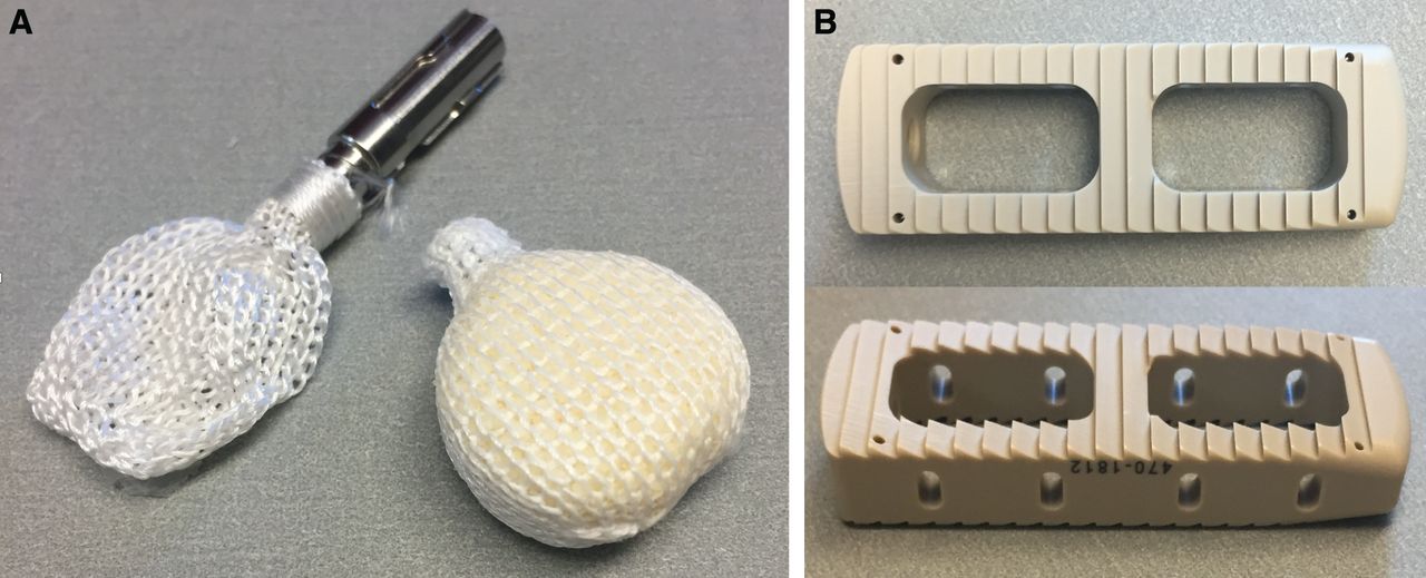
(A) Conformable porous mesh device unfilled and filled. (B) Lateral PEEK cage.
Four each of the CPM and LPC devices were filled with human allograft bone as per the manufacturers' recommendations. All of the filled implants were tested at 3 compressive load levels; 1100, 2000 and 3000 N. Prior to compressive loading of the constructs filled with bone, the larger LPCs were intentionally overfilled with repetitive manual compression of the bone into the open core structures of the cage to provide an “overfilled” advantage for this construct (Figure 3). LPC was filled with granular graft until the graft was hypercompacted and rigid.
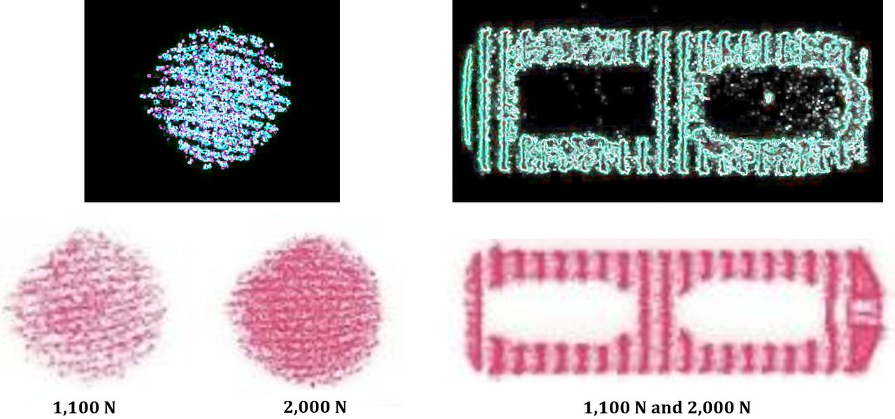
Pressure impressions and threshold images for the conformable porous mesh device and the lateral PEEK cage.
The construct for each test consisted of a device sandwiched between 2 Grade 15 PCF polyurethane foam blocks to simulate the vertebral body and endplate cancellous bone. Pressure-sensitive film was placed between the superior and inferior endplates and foam bone blocks for each implant construct. Pressure-sensitive film of low and medium threshold grade were initially analyzed to determine the appropriate pressure range for testing. The low-pressure film was identified as the appropriate range for all constructs tested (SensorTek pressure-sensitive film, FujiFilm Prescale and Topaq, Sensor Products Inc, Madison New Jersey). Each of the filled interbody devices was compressed between the 2 foam bone blocks at a rate 0.1 mm/s for 3 consecutive applied compressive loads (1100, 2000, or 3000 N). The pressure sensitive film was changed at both the superior and inferior interfaces after each load application.
Images of each pressure profile were captured using digital photography and imported into image analysis software (ImageJ Version 1.51k, National Institutes of Health, http://imagej.nih.gov/ij). Every digital image was calibrated to markers of known dimensions, followed by cropping of each image to the specified region of interest. Area measurements were taken after applying threshold parameters using the image analysis software to isolate the contact footprint area for every sample. The contact area under compressive load for the bone graft communicating regions were also directly measured to provide further verification and were congruent with the threshold results (Figure 4).
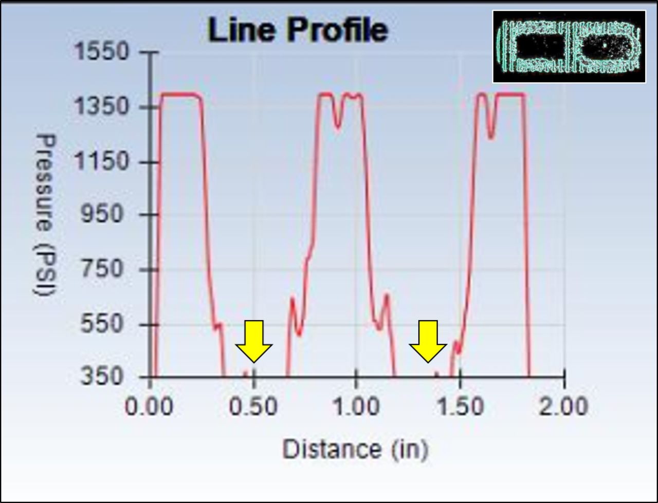
Line profile for the PEEK cage under 2000 N of compressive load. Negligible bone graft material was loaded as indicated by the lack of any measurable pressure at the bone communicating cores of the implant (arrows).
Part 2: FDA IDE Study: Radiographic Assessment
When assessing new technology, clinicians require that improvement not come at the expense of current clinical success; hence, CPM clinical success measures must meet at a minimum current fusion success criteria. To that end, a prospective, multicenter, single-arm FDA IDE (NCT02347410) trial of the CPM was conducted to determine if the novel CPM design altered expected clinical success. Ninety-six (94% follow-up rate) subjects' (57.0 ± 12.0 years, 50.0% female, body mass index 30.6 ± 4.9) serial flexion and extension radiographs and CT scans were evaluated by 2 independent board-certified radiologists to determine fusion status. All patients underwent instrumented lumbar IBF to treat degenerative disc disease at a single level between L2 and S1. Fusion was defined as bridging bone across the intervertebral space extending from endplate to endplate and less than 5 degrees of relative angulation and less than 3 mm of translation between flexion and extension x-ray measurements. If there was disagreement regarding fusion status, a third radiologist's evaluation was used to adjudicate the case.
A qualitative assessment of the 12- and 24-month CTs for a series of patients was evaluated for additional radiographic identifiers indicative of biomechanical responses to fusion healing. The conventional fusion criteria for these patients were met. However, further critical assessment of the surrounding vertebral bone and the bone healing patterns at the vertebral endplates was conducted with similar findings observed in the majority of patients involved in the clinical study. These radiographic indicators represented the biomechanical principles first established by Julius Wolff in the 1800s where adaptive changes in the bone architecture will occur when bone or other tissue is exposed to changes in stress. Structural adaptation of the tissue in response to changes in the loading stimuli will occur where the changes occur along the applied lines of stress, resulting in an increase in local bone densities in the presence of increased stress or resorption in the absence or decline in stress. Radiographically, these are located through radiographic image intensities.
Parts 1 and 2: Statistical Analysis
The contact area results for both devices were descriptively analyzed due to small sample size. Pressure maps were generated from the load profiles using Topaq software (Sensor Products Inc). Given the single-armed study design, fusion data were also descriptively analyzed.
RESULTS
Part 1: Load Profile Study
The mean direct contact area measured for CPM was 341.2 ± 9.5 mm2 at 1100 N, 359.7 ± 16.2 mm2 at 2000 N, and 556.8 ± 9.0 mm2 at 3000 N of compressive loading and represented the direct loading of the bone graft material within the device. Contrary to this and despite the presence of graft material in the open cores of the monolithic PEEK lateral interbody cage, the bone graft–containing portion of the device left no discernible impression on the pressure-sensitive film at 1100 and 2000 N. However, at the higher 3000 N of loading, there was minor visible stipulation present on the pressure film, indicative of a negligible amount of measurable pressure. Pressure profile analyses, as shown in Figure 2, demonstrated the lack of direct bone graft loading held within the open cores of LPC. Assuming that full loading of the bone graft had occurred, a default area for maximum bone exchange was 151 mm2 and represented the full maximum area of the open cores of the implant. However, the line profile represented the lack of direct bone graft loading, as identified by the minimal pressure recorded in the bone communicating region. See Figure 3.
Part 2: Radiographic Assessment
CPM fusion rates were 97.9% (94/96) at 12 months and 99% (95/96) at 24 months with a corresponding mean decreased low back pain from baselines of 50.6 and 51.4, respectively.12,13 While the literature is replete with similarly executed analyses of lumbar spine fusion, the novel aspect of our current evaluation of these images is a qualitative assessment of identifiable regions of structural responses to achieve homeostatic adaptation. These radiographic signs were identified on the CT scans at 12 and 24 months postoperation. Radiographic identifiers were observed in the form of radiating struts of bone that traverse the vertebral endplate into the pores of the conformable porous interbody device (Figure 5). These radiating struts are clearly visualized at 12 months with further maturation and greater densification at 24 months in the representative intrasubject serial CTs. These struts form a 3-dimensional network of bone ingrowth bridging from the vertebral endplates into the pores of the conforming implant. The visible bone struts traversing from the endplates into the conforming device displayed greater surface area of this “bridging bone” across the contacting surface of the implant at the endplate, as shown in the sagittal and coronal CT views. A greater surface area of direct contact provides better stability due to distribution of the axial forces across a larger surface area, thereby optimizing the biomechanical environment for fusion healing.
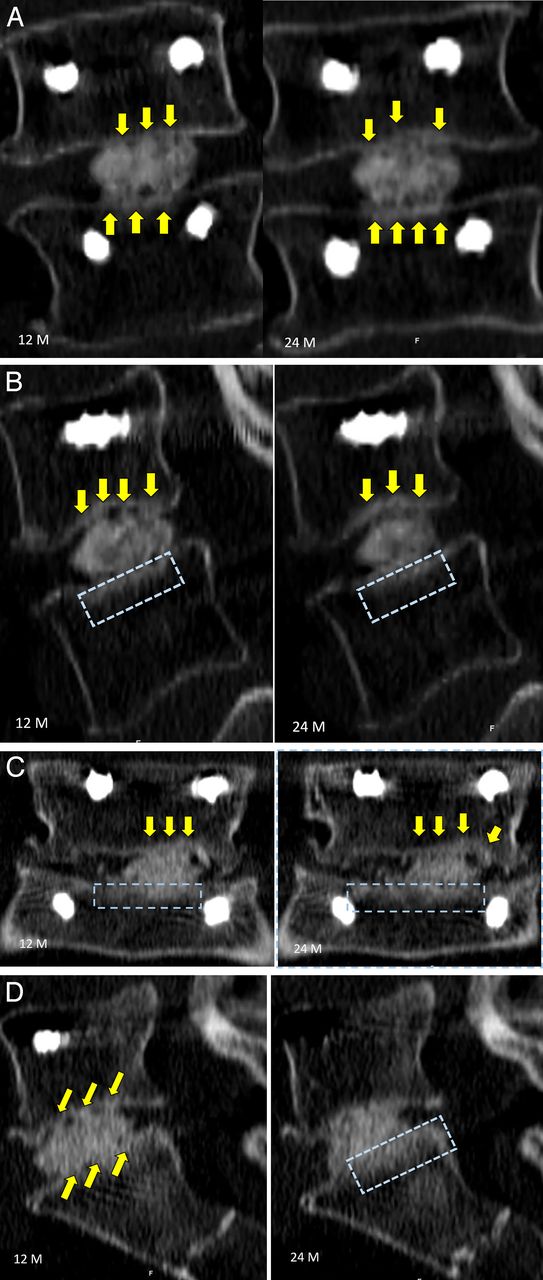
Case examples of radiographic identifiers and assessment. Yellow arrows identify regions of radiographic struts of bone from the vertebral endplate to the conformable porous mesh with bone graft material, and the blue rectangle demonstrates regions of radiographic intensity representing regions of denser bone.
A second identifying radiographic marker that provides biomechanical evidence of structural adaptation in response to changing stresses across the fusion site can be observed as regions of greater intensity in the surrounding bone and at the peripheral bony margins. In the presence of increased loads, more bone is formed to compensate for the greater localized forces. This will occur in the presence of healing bone, such as that across a stable fusion site, but also in spinal degeneration, where bone is formed in regions where stresses are transferred due to degenerative structures that lose mechanical integrity. These radiographic identifiers may be temporary interim markers that may eventually disappear in the presence of restoration of load balance across the fusion site, resulting in remodeled organized bone formation. Figure 4 also identifies regions in these same patients exhibiting osseointegrated struts across the fusion site where the bony margin of the vertebral endplates were thickened. These regions were indicative of areas of increased lines of stress that were visible in the surrounding vertebral cancellous bone along the lines of the osseointegrated struts during the healing process.
DISCUSSION
There are numerous expandable IBF devices currently on the market, each with its own unique design characteristics. However, the basic principles of achieving IBF success rely not only on implant design features but also on numerous additional factors that must interact with the implant and graft material in a synergistic manner.6,14,15 Unfortunately, it is difficult to include design factors into 1 implant that will address all of the basic principles to achieve successful fusions. Therefore, it is best to incorporate a few key design features that will maximize the chance for a successful fusion in the presence of the multitude of variability that exists between patients.15,16
Design strategies such as conformity, contact area, open architecture (ie, pores) to allow for multidirectional bone ingrowth, and direct loading of the graft material were shown to be factors for bone healing success and further fusion formation, as indicated by the conformable porous mesh. A large footprint implant with maximum surface area of the exposed graft material that is in direct contact with the vertebral endplate would provide improved interface micromechanics and reduced stress transfer to surrounding tissue structures. Conforming or curved implant shapes on the bone communicating surfaces lessen the work required by the viscoelastic vertebral endplates to flex and conform to the implant versus the inverse scenario.17 Furthermore, distribution of the vertebral endplate loads over a greater area results in lower stresses on the endplates and reduces the risk of subsidence. This is especially important in the degenerative and osteoporotic spine, where the mechanical properties of the endplate are compromised and have lower strength thresholds. However, it is important to note that other, alternative design strategies may also exhibit significant influence on bone healing for different IBF technologies.
Radiographic identifiers in this study were illustrative of the biological response to the biomechanical environment.18 The vertebral endplates demonstrated radiating bone struts traversing the endplate into the pores of the CPM. Ancillary observations were thickened endplates and regions of increased intensities, and striations into the vertebral bodies extending from the vertebral endplates were also observed in the series of follow-up CT scans at 12 and 24 months. These identifiers serve as the radiographic cues that identify the process of structural adaptation of the bone surrounding the fusion site and at the interface of the vertebral endplate and implant and are suggestive of the dynamic changes in supportive stresses during the bone healing process. Correlating the radiographic findings and area of loaded graft material with the biomechanical environment may provide further insight in support of the positive clinical outcomes measured.
CONCLUSIONS
Understanding basic principles such as contact area, graft loading, and conformity that affect fusion healing is the key to implant selection and, ultimately, fusion success. While no implant can possibly include every optimized design parameter without suffering compromise elsewhere, it is critical for surgeons to consider which parameters are most important for the specific patient being treated and if/how multiple parameters can be optimized to synergistically affect the biomechanical environment of lumbar spine fusion. Radiographic identifiers can provide biomechanical evidence of the bone healing status across a fusion site, giving the necessary clues to achieving the balance between time to heal and fusion site stability. Surgeons can in turn use this feedback in concert with individual outcomes to inform future patient care.
Footnotes
Disclosures and COI: The first through fifth authors are paid consultants from a company involved in the manufacture of a device examined in this study.
- This manuscript is generously published free of charge by ISASS, the International Society for the Advancement of Spine Surgery. Copyright © 2020 ISASS
In this issue


Jump to section
Related Articles
Cited By...
- No citing articles found.