


ABSTRACT
Background: During the past decade there has been a significant increase in the number of vertebral fractures being treated with the balloon kyphoplasty procedure. Although previous investigations have found kyphoplasty to be an effective treatment for reducing patient pain and lowering cement-leakage risk, there have been reports of vertebral recollapse following the procedure. These reports have indicated evidence of in vivo bone-cement separation leading to collapse of the treated vertebra.
Methods: The following study documents a multiscale analysis capable of evaluating the risk of bone-cement interface separation during lying, standing, and walking activities following balloon kyphoplasty.
Results: Results from the analysis found that instances of reduced cement interlock could initiate both tensile and shear separation of the interface region at up to 7 times the failure threshold during walking or up to 1.9 times the threshold during some cases for standing. Lying prone offered the best protection from interface failure in all cases, with a minimum safety factor of 2.95.
Conclusions: The results of the multiscale analysis show it is essential for kyphoplasty simulations to take account of the micromechanical behavior of the bone-cement interface to be truly representative of the in vivo situation after the treatment. The results further illustrate the importance of ensuring adequate cement infiltration into the compacted bone periphery during kyphoplasty through a combination of new techniques, tools, and biomaterials in a multifaceted approach to solve this complex challenge.
- kyphoplasty
- vertebral compression fractures
- multiscale finite element analysis
- micro-CT
- bone-cement interface
INTRODUCTION
Since the advent of balloon kyphoplasty for the treatment of vertebral compression fractures in 1998, the rate of uptake by clinicians has significantly increased, with an average of 45 000 cases per annum during a 5-year period in the United States alone.1,2 The procedure was introduced as an improvement on first-generation vertebroplasty, which was predominantly focused on fracture stabilization rather than deformity correction. Kyphoplasty provides active deformity correction by using an inflatable balloon to decompress the collapsed vertebra. A further benefit of the balloon expansion process has been an associated reduction in the incidence of cement leakage due to the reduced injection pressure of cement into the cavity created by the balloon.3 In tandem with the high rate of use by clinicians, a significant volume of corresponding literature has been documented regarding the efficacy of the treatment in reducing patient pain.4,5 Whereas restoration of mechanical factors such as vertebral height, strength, and stiffness have also been extensively studied after the treatment, a universal consensus on the sustainability of these improvements remains absent.6–10
Adjacent-level fractures constitute one of the most discussed aspects of the treatment, with several studies indicating a high rate of additional fractures ranging from 14%–33% within the initial 60–90 days after the treatment.11–16 It has been further suggested that an elevated risk of recurrent fracture exists after kyphoplasty compared with the natural course of progression.13,14 Whereas many of these studies have previously focused on the integrity of the adjacent vertebrae, there are an increasing number of reports that indicate the potential for recollapse of the treated vertebra itself after surgery.12,17–20 Many authors have attributed these recollapse events to an insufficient mechanical interlock between the host bone and the injected cement.17,19
This hypothesis has been supported by evidence of discontinuity between the injected cement and the surrounding bone in vivo through the use of dynamic radiographs.20 Another radiological study of 175 kyphoplasty cases also indicated a 78% rate of recollapse in patients with an observable “halo” at the interface between the host bone and injected cement within 7 days of the treatment.12 A likely factor contributing to these occurrences may be the reduced cement interdigitation achieved by kyphoplasty due to compaction of the trabecular bone by the balloon, which creates a barrier to cement infiltration.21–23 These findings are further supported by postmortem histological studies that have observed a thin fibrous membrane and necrotic bone adjacent to the compacted region.24 Combined with the knowledge that many fractures occur before bone repair has matured, it is likely that this creates an environment that facilitates recollapse.25
Mechanical evaluations of the bone-cement interface have predominantly focused on hip replacements in which aseptic loosening ranks among the top causes of implant failure.26,27 Experimental and microfinite element (micro FE) investigations have illustrated the importance of proper cement infiltration into the bone structure to attain a sufficient tensile and shear strength to ensure the integrity of the bone-cement interlock.28,29 Conversely, compressive strength of the interface has been found to be independent of penetration depth with failure initiating at the interlocks of cement and bone in the partially interdigitated region, where localized trabecular buckling dominates.30,31 The presence of microscopic gaps between the bone and cement, such as those reported following kyphoplasty,21 can significantly diminish the interfacial strength even in cases of good interdigitation.32 Trapped fluid within these microscopic gaps have also been implicated in causing fluid-induced lysis of trabeculae, which can further erode the integrity of the interface.33
One of the few studies that specifically examined vertebral trabecular bone augmented with cement found the apparent strength and stiffness of the composite was lower than that of bulk cement.34 The authors recommended that future macroscale computational models examining cement augmentation should assign specific properties for the bone-cement interface rather than assume a step change from the bone to cement domains without any intermediary properties. To our knowledge only 2 other kyphoplasty models have explicitly represented the interface as a layer of elements surrounding the cement with an intermediary modulus assigned.35–38 The majority of macroscale kyphoplasty simulations instead assume an instantaneous transition of elastic properties from bone to cement via shared node bonding of the domains.39–43 These assumptions would not have been deemed unreasonable before the more recent in vivo observations of bone-cement interface separation. These clinical reports require consideration that modeling the complex mechanical behavior of the interface requires specific attention to reliably evaluate changes in the load distribution of treated spine segments.
A complete mechanical appraisal of the kyphoplasty treatment thus necessitates the development of a multiscale model capable of capturing both the global spine mechanics in tandem with the complex micromechanical interaction of the bone-cement interface. The current study aims to provide such a model to assess whether in vivo loading conditions following kyphoplasty could be sufficient to initiate separation of the bone-cement interface during normal daily activities such as walking.
METHODS
Two stages of computational modeling were required to determine whether spine segment loads during normal daily living could induce separation of the bone-cement interface. In the first part, a micro FE model of a treated vertebral body with a strain-dependent material model was developed to establish the tensile (Mode I) and shear (Mode II) properties of the interface. Results from this analysis were then used in the second part to define the contact properties of a macroscale spine model subjected to lying, standing, and walking loads after treatment with kyphoplasty.
Generation and Setup of Microscale Computational Models
Creation of the micro FE model of kyphoplasty used an open-source image processing package ImageJ44,45 and a freely available dataset for an L3 vertebral body.46 After thresholding of the data, binary image subtraction was used to bilaterally locate 2 cement volumes that were scanned in a previous kyphoplasty study with a resolution of 32 μm. A 3-dimensional thinning algorithm was applied to generate a skeletonized representation of the bone structure, which would be otherwise too complex to generate a feasible solid element mesh.47 The skeletonized structure (Figure 1) was subsequently converted into a beam element model using custom code written in ANSYS Advanced Parametric Design Language (APDL). Each beam element was assigned a circular cross-section such that the volume of the original bone structure and the beam-element model were equivalent. Meanwhile, the cement and cortical shell were meshed using solid tetrahedral and hexahedral elements, respectively. Connection between the beam and solid elements was established using translational degree of freedom coupling for nodes nearest the beam-solid interfaces, referred to as full interlock. The effect of reducing the number of coupling points at the bone-cement interface by 90% was also studied to simulate cases of poor cement interlock, a process referred to herein as reduced interlock.

Micro FE model of bilateral kyphoplasty with beam and solid elements. FE, finite element.
Material properties for the bone structure were applied using a previously documented strain-controlled modulus reduction algorithm capable of representing the stiffness loss due to material damage.48–51 The stress-strain relation described by Equation 1 allows a continuous nonlinear transition from elastic to perfectly plastic behavior. The material model was incorporated into the ANSYS solver using the USERMAT subroutine.

 where β = [E0ε*/σ0]m; E0 = 15 GPa; υ = 0.3; σ0 = 70 MPa; and m = 1.
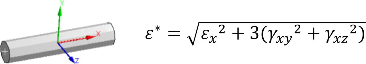
And the equivalent strain ε* for the ANSYS BEAM188 element was derived using the von Mises criteria as follows (see Figure 2).

BEAM188 element coordinate system and equivalent strain computation.
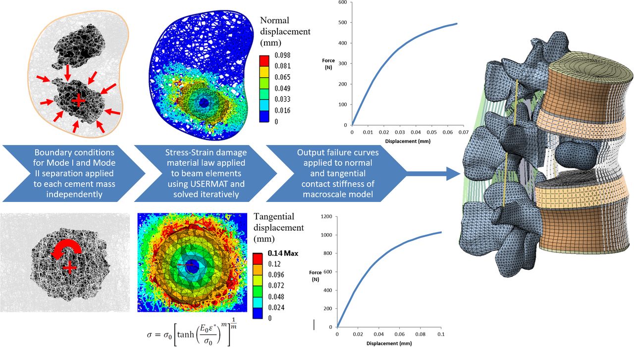
Mode I tensile separation of the interface was modeled by applying a uniform volumetric reduction of each cement mass about its centroid, as illustrated in Figure 3. Applying such a condition induced a displacement towards the cement centroid, thus simulating tensile separation of the interface. Mode II shear separation was simulated by applying a tangential rotation to the cement mass within the trabecular structure, thereby inducing shear at the interface. All boundary conditions were applied iteratively in 25 equal steps. Nodal displacements and reaction forces of the interface region were extracted during each analysis step to enable the corresponding macroscale stiffness and strength properties to be calculated for each mode of separation. Strength properties were derived on the basis of the reaction loads at which stiffness loss reached 90%, along with the corresponding surface areas of each cement mass.

Generation of beam element models after skeletonization of computed tomography data and applied boundary conditions for Mode I tensile and Mode II shear separation. Failure curves output from the micro FE analysis were applied in the macroscale model by explicitly defining the normal and tangential contact stiffness between the bone and cement domains. FE, finite element.
Generation and Setup of Macroscale Computational Models
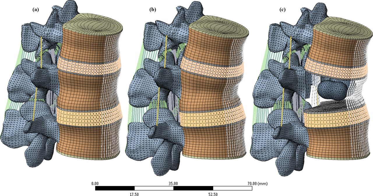
The macroscale part of the analysis used a finite element model of the thoracolumbar spine that has been extensively documented and validated directly with an experimental study that included the specimen from which the model was built.52–54 For the present analysis, the model was reduced to 2 motion segments (Figure 4) centered on the first lumbar vertebra (L1). Alterations to the validated model setup were minimized by retaining the same mesh and reference nodes for application of the boundary conditions; whereas, geometric modification was limited solely to the interior L1 trabecular compartment. A bilateral kyphoplasty treatment was replicated in the model by remeshing the interior of the L1 trabecular compartment to include 2 cement masses while maintaining connectivity with the surrounding original mesh. Numerical verification of stress results for the remeshed region was achieved using the nodal fraction quantity in ANSYS, which enabled the magnitude of stress-field discontinuity to be evaluated. Using this approach ensured that the integrity of the previously conducted validation studies of the model were retained.55

(a) Finite element model of thoracolumbar junction T12-L1-L2 in healthy intact state. (b) Model with simulated wedge fracture at L1. (c) Wedged model with bilateral kyphoplasty at L1 with cortical and trabecular components hidden for clarity.
The completed model consisted of 3 vertebrae articulating between 2 pairs of fiber-reinforced discs and 4 facet joints with frictionless surface-to-surface contact. The 9 ligaments of the spine were also included with either variable (COMBIN39) or constant stiffness (LINK180) tension-only struts that serve to stabilize the structure (Table 2). The nucleus pulposus of the intervertebral discs were modeled using incompressible hydrostatic fluid elements (HSFLD242). The surrounding annulus matrix, meanwhile, used a Mooney-Rivlin hyperelastic formulation reinforced with 4 layers of fibers with varying stiffness from the inner to outermost rings (properties in Table 1).
Summary table of 3-dimensional solid element types and material properties in macroscale model.
Soft tissue properties for macroscale model.
Two cement volumes of 2 mL and 6 mL were modeled to examine the influence of cement volume on separation characteristics. These models were paired with a further 2 configurations either with or without consideration of the fracture shape, thus resulting in a total of 4 kyphoplasty models. The 2 models without fracture simulation remained consistent with the healthy intact model, except for the addition of 2 bilateral cement masses. Incomplete restoration was simulated in the fractured models by applying a 10° wedge angle to the treated vertebra along with replication of a Magerl type A3 fracture pattern by assigning a reduced modulus of 15 MPa to the elements along the fracture path.56,57
Modeling separation of the bone-cement interface required the meshes of the injected cement and the surrounding trabecular bone to be created independently without sharing any element connectivity. Load transfer between the 2 domains was instead achieved using a penalty-based contact formulation with CONTA174 and TARGE170 contact elements that were overlaid on the free faces of the elements at the interface. The normal and tangential stiffness of the interface bond was then assigned using the results of the micro FE study, thus incorporating the micromechanical response of the interface into the macroscale model.
To maintain consistency with the boundary conditions applied in the original validation study, lying and standing conditions were replicated in the model by fully constraining the inferior endplate of L2 while follower loads of 144 N and 800 N were applied through reference nodes on the sides of each vertebral body.58 The applied follower-load direction remained aligned with the spinal curvature by iteratively updating the local coordinate system of the reference nodes until the motion segments reached their final equilibrium positions. Walking was simulated on the basis of in vivo data by increasing the follower load by a further 30% to 1140 N in conjunction with applying a torsional moment of 7.5 Nm to the superior endplate of T12.59,60
RESULTS
Micro FE Model
Results for the tensile (Mode I) and shear (Mode II) separation simulations presented in Figure 5 show the failure responses before and after application of the reduced interlock criteria (outlined in the “Generation and Setup of Microscale Computational Models” section). Examination of the responses for each loading mode illustrates the increased resistance of the structure to shear separation compared with tensile separation.
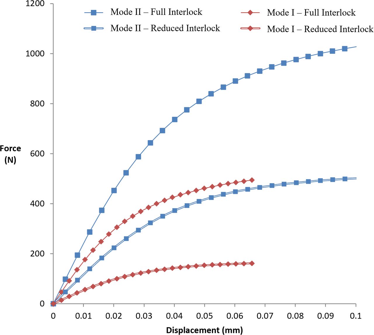
Mean bone-cement interface separation response for the cement masses with full interlock and reduced interlock applied.
Comparison of the data presented in Table 3 shows shear strength and stiffness were reduced by amounts of 50.5%–53.1% and 45.9%–46.5%, respectively, when poor cement interlock was simulated. Tensile separation behavior exhibited greater reductions in stiffness spanning 66.1%–63.3%, whereas strength values showed comparable decreases of 66.4%–68.9%. Shear strength was consistently higher than tensile strength by a factor of approximately 2 with full interlock, increasing to a factor of 3 under reduced interlock conditions. Corresponding relations for shear stiffness showed similar trends, with factors of approximately 1.4 with full interlock applied and up to 2.15 with reduced interlock.
Comparison of mechanical properties between full and reduced interlock simulations.
Macroscale Model
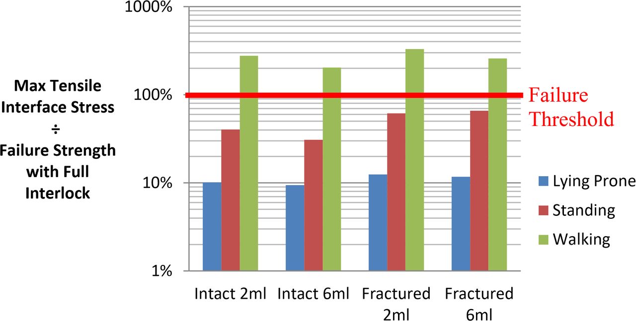
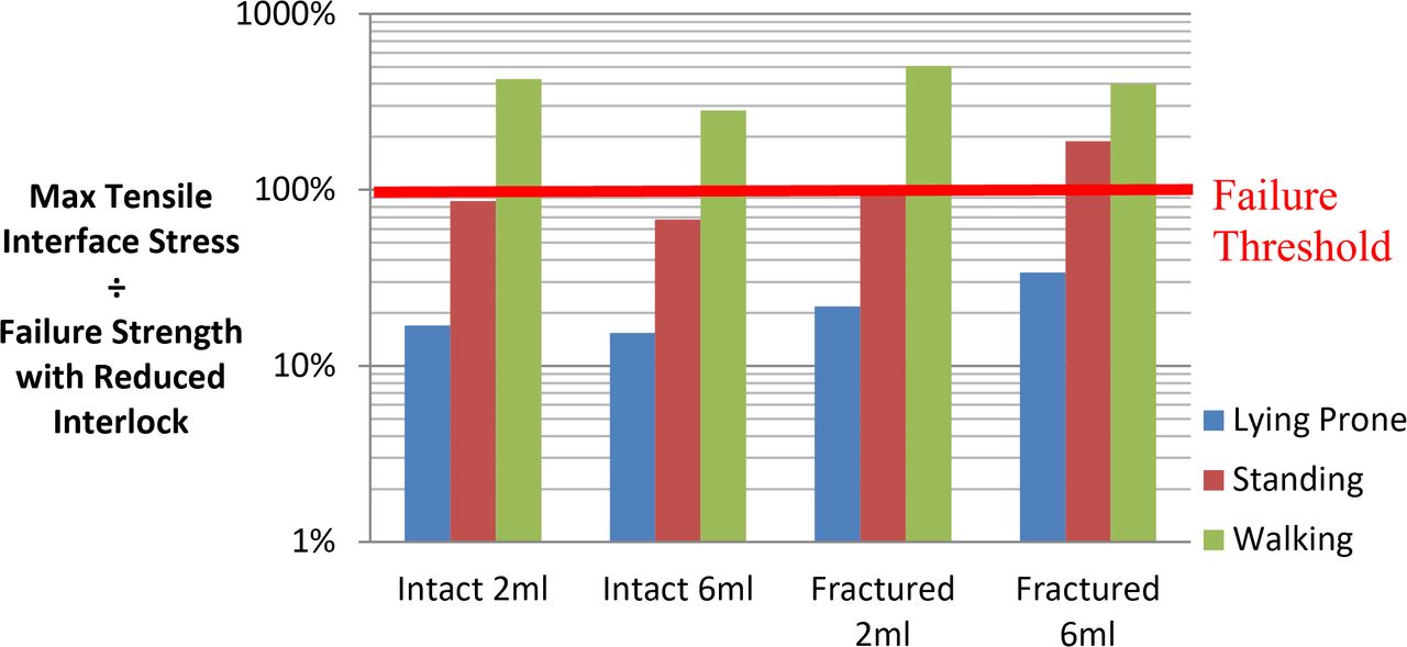
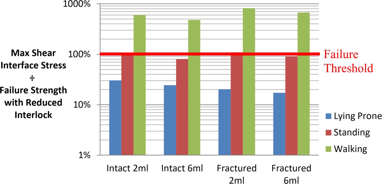
Stress results from the macroscale models for each mode of separation with full and reduced interlock properties applied are presented in Figures 6–9. These macroscale stress results were normalized against the predicted failure strength from the micro FE analyses for the particular mode of loading and interlock configuration, as outlined in Table 3.

Mode I tensile separation stress normalized to failure strength with full interlock.
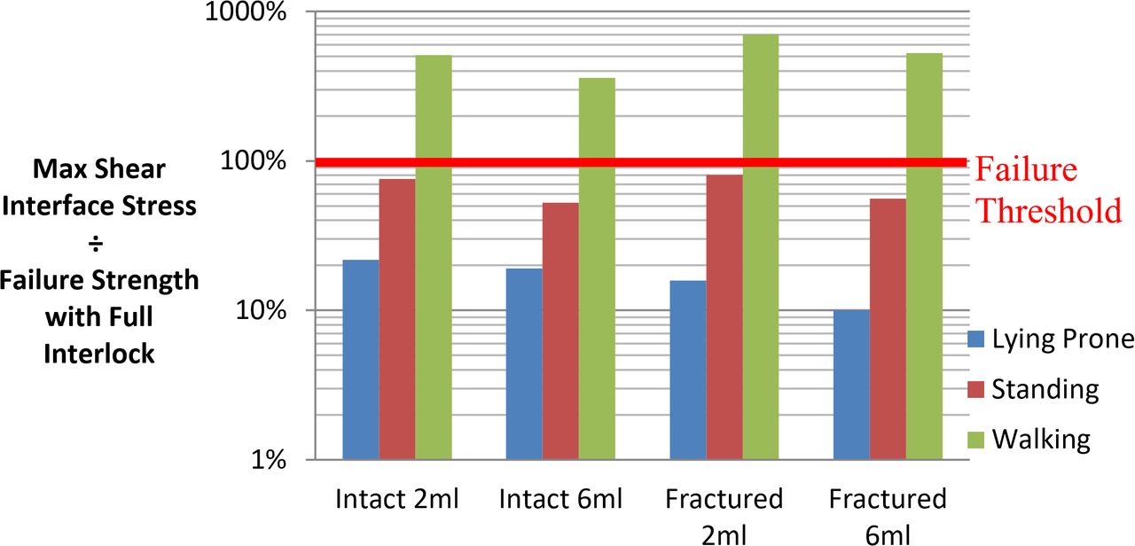
Mode II shear separation stress normalized to failure strength with full interlock.

Mode I tensile separation stress normalized to failure strength with reduced interlock.

Mode II shear separation stress normalized to failure strength with reduced interlock.
Macroscale Model With Full Interlock
Walking loads were predicted to induce separation of the interface with stresses exceeding the threshold by factors of 2.04–3.3 for tension and 3.6–7 for shear. Conversely, lying and standing loads were predicted to be within the failure threshold for all full interlock cases with factors ranging from 0.094–0.804. Load factors were generally higher for shear than tension by an average of 81% for all models except for the fractured 6-mL model under lying and standing conditions, which were both lower by approximately 15%. Increasing cement volume lowered shear load factors by an average of 27%, whereas tensile load factors decreased by an average of 17%, excluding the fractured 6-mL model, which indicated a 7% increase.
Macroscale Model With Reduced Interlock
Application of reduced interlock at the interface increased load factors for all cases by an average of 64%. Walking loads were found to be sufficient to cause failure through both modes of separation and were increased by an additional margin of 37% compared with the full interlock case. Shear load factors exceeded those of tension by an average of 46%, excluding the fractured model configurations with lying and standing conditions applied, which showed decreases up to 52%. Standing loads were sufficient in half of the models studied to induce separation through either tensile or shear loads. In the case of the fractured 2-mL model, both tensile and shear stresses exceeded their allowable limits for standing loads alone. Higher cement volumes were found to lower tensile and shear load factors by an average of 20% excluding the fractured 6-mL model. Lying prone was found to offer the best protection from interface separation, with a minimum safety factor of 2.95 for the fractured 6-mL case.
DISCUSSION
Micro FE Model
Evaluation of the micro FE results presented in Figure 5 illustrates the impaired ability of the interface region to resist shear and tensile separation in cases of reduced cement interlock. Previous literature reports of lumped mass cement distributions and poor interlock indicate that cases of inhibited bonding are not only possible but potentially prevalent after kyphoplasty.21–23 Strength reductions ranged from approximately half to two-thirds for shear and tensile loading, respectively, demonstrating the need for macroscale models to account for the micromechanical behavior of the interface. Although replicating poor interlock by reducing the number of coupling points by 90% may seem excessive, clinical reports indicate that such scenarios are indeed feasible in cases of “lumped” cement distributions.23 To what extent the cement distribution must be lumped to result in a negligible bonding response, however, remains unknown.
Consistent with previous studies of bone-cement interfaces in the human femur, the micro FE analysis of the interface found that the structure was considerably stiffer and stronger in shear than in tension (Figures 6–9).64 The previous experimental study found shear strength exceeded tensile strength by factors ranging from 1.7–2.5 compared with the present analytical finding of approximately 2.29,64 Similar trends were observed for the stiffness properties of the interface at 16.2 MPa/mm for shear and 11.8 MPa/mm for tension. These magnitudes were within the range of previous data29 for penetration levels <1 mm, indicating a shear to tension ratio spanning 1.26–2.06.
A rationale for the apparent disparity between tensile and shear properties has been hypothesized to relate to the pullout mechanism of the interdigitated bone pedicles from the cement mantle. This mechanism has been suggested to be more efficient in the case of tension.65 We find it interesting that this indicates the mode of failure also likely contains an additional global contribution from the surrounding bone struts because the present micro FE analysis does not explicitly model these pullout mechanisms.
Macroscale FE Model
Examination of the macroscale model results presented in Figures 6–9 shows a high risk of bone-cement interface separation during walking, even in cases of good interlock. Cases of reduced interlock, meanwhile, were found to present a risk of bone-cement interface separation even during standing loads. The risk of separation was lowest in the case of a vertebra with full deformity correction and a high cement volume. Further investigation of cases of high cement volume found that this behavior was driven by a redistribution of the load over a larger cement area, which in turn reduced the load intensity at each interdigitation site between the trabeculae and the cement mantle, consequently lowering the risk of debonding initiation. Whereas higher cement volumes may reduce the risk of separation, many authors66,67 have suggested that excessive cement volumes could be detrimental to treatment outcomes. These suggestions have been founded on the hypothesis that larger cement volumes render the treated level excessively stiff, thus elevating the risk of adjacent vertebra failure. More recent investigations have found that any adjacent-level effects are strongly dependent on achieving endplate-to-endplate cement contact, which is often not the case following kyphoplasty.19,68–70 The latter of these studies found that cases without endplate-to-endplate contact exhibited localized bands of bone damage above and below the cement mass. Furthermore, applying the principles of “weakest link” probability theories such as the Weibull distribution, as often applied to brittle materials, could also suggest that a larger cement volume would increase the number of potential locations at which failure could initiate. Such complexities are, however, beyond the scope of the present study and are instead noted here as a potential path for future study.
The highest risk of interface separation was predicted for models without deformity correction combined with reduced interlock. It is interesting that higher cement volumes in these cases increased the risk of tensile pullout during lying and standing by an average margin of 69% yet reduced the risk during walking by 21%. Consideration of this behavior indicates a contribution of fracture shape to the response because equivalent changes were not observed for the intact models.
Further investigation of this result characteristic revealed a shift in the location of tensile separation from the posterior cement regions to the anterior parts. This was attributable to the reduced constraining capacity of the fractured cortical shell, which, combined with the closer proximity of the cement masses in the 6-mL fill case, intensified tensile separation loads in the anterior regions of the interface.
An overview of all results from the macroscale analyses indicates a significant risk of overloading the bone-cement interface during the recovery after kyphoplasty at a time when bone remodeling processes are ongoing but have yet to establish viable bone with a load-bearing capacity.25 Whereas the results would suggest that lying prone offers the best protection against overloading the interface, this is obviously not a suitable solution from a clinical perspective. The results instead highlight the need to develop strategies that ensure adequate cement infiltration into the compacted bone periphery during kyphoplasty such that a mechanically stable interlock can be established. Achieving such an outcome is not a trivial task, however, since improved cement infiltration is usually associated with increased injection pressures and pulmonary embolization risk. Novel approaches to the kyphoplasty procedure such as the “eggshell technique” proposed by Greene et al71 and radio frequency–augmented kyphoplasty are just 2 examples of techniques that could serve to enhance the properties of the bone-cement interface in a safe manner.22 Alternative devices such as the Kiva implant and vertebral body stenting, meanwhile, also offer new options for restoring vertebral height in a manner that fundamentally alters the nature of the bone-cement interface and thus may avoid some of the issues highlighted by the present study.72,73 Furthermore, new biomaterial formulations also may offer the potential of achieving fusion at the interface and ultimately a capacity to remodel with the surrounding trabecular architecture.74
Study Limitations
Results from the present study highlight the importance of characterizing the mechanical behavior of the interface to address clinical observations of bone-cement discontinuity and the subsequent collapse of treated vertebrae. The analyses also show that the risk of interface separation can be significantly mitigated by ensuring sufficient cement infiltration into the compacted bone periphery during kyphoplasty while carefully managing load exposure, given that bone remodeling processes are ongoing but have yet to establish viable bone within the first 8 weeks in particular.25 Although there is extensive agreement of the computational models with published literature, the following limitations of both the micro FE and macroscale methods are acknowledged.
Modeling the complete trabecular structure required the use of a skeletonization algorithm to generate a beam element representation of the structure.47 The use of skeletonization methods has previously been suggested75–77 as an effective means of accounting for the micro-architectural complexity of trabecular bone while being computationally efficient enough to permit whole bone analyses such as those in the current study. The present study assumed direct connectivity of the skeleton node points using straight beam elements with a circular cross-section. These compromises were deemed reasonable because morphological studies have found vertebral bone to consist predominantly of rod- rather than plate-type trabeculae, unlike the femur where a significant proportion of platelike trabeculae exist.78
Parameters for the material model presented in the “Generation and Setup of Microscale Computational Models” section were assigned within the range of previous experimental studies on trabecular tissue with an elastic modulus of 15 GPa and a yield strain of 0.62%, which was controlled by the stress asymptote σo and damage index m.79,80 Resulting apparent yield strains of 0.88% and stresses of 0.879 MPa for the whole trabecular structure were within the range of experimental data for human vertebral bone.81 Thus, the baseline behavior of the beam model before augmentation was deemed to be consistent with the mechanical behavior of vertebral trabecular bone, albeit while assuming symmetry of properties in tension and compression.
Micro FE modeling of the augmentation stage of the treatment, meanwhile, required the following compromises to make the simulation feasible. First, the interface separation characteristics presented in Figure 5 assumed the 2 modes of separation were independent of each other without any mixed mode effects. Second, load transfer between the bone elements and the solid cement elements was achieved via degree of freedom coupling, thus removing the ability to account for micromotion at the individual trabecula level.
Modeling the balloon expansion process within the trabecular network would also have been desirable; however, the additional complexity of such an analysis was beyond scope of the present study. A conservative approach was instead adopted by assuming no initial material damage after augmentation.
The macroscale model also necessitated assumptions shared by many FE models of the spine such as homogeneous continuum properties and the application of follower loads to replicate in vivo stabilizing muscle forces. Due to using this follower-load approach, our model omitted the role of muscle compensation mechanisms in absorbing and stabilizing loads throughout the spinal column. Investigation of endplate stress distributions and adjacent-level fractures was also beyond the scope of the present study, given that the primary focus was to consider recollapse of the treated level. Nucleus pulposus pressures of 0.475 MPa and 0.531 MPa in our baseline untreated model for standing loads also showed excellent agreement with in vivo disc pressure measurements58,82 These findings, combined with the considerable previous work to validate the model directly with specimen-specific tests, allows confidence that the behavior of the baseline model before augmentation was representative of the in vivo situation.
Modification of the model to replicate the augmented case was carefully conducted to preserve the integrity of the previous validations by isolating changes in the model solely to the newly meshed L1 trabecular centrum incorporating 2 cement masses. It is important to recall, however, that the geometry and volume of the cement masses were also idealized to 2 fixed volumes of 2 mL and 6 mL.
CONCLUSIONS
The significant risk of interface separation suggested by the present study supports the hypothesis that interface separation cannot be discounted as a contributory factor in the recollapse of kyphoplasty-treated vertebrae. It is therefore recommended that future macroscale simulations of the treatment should be capable of detecting interface separation and its subsequent effects on load transfer within treated vertebrae. These results further illustrate the importance of ensuring adequate cement infiltration into the compacted bone periphery during kyphoplasty so that a mechanically stable interlock can be established. Achieving such an outcome in a safe manner requires a multifaceted approach with the development of new techniques, tools, and biomaterials to all play a role in solving this challenging issue.
Footnotes
Disclosures and COI: This study was funded by the Irish Research Council EMBARK Postgraduate Scholarship RS/2011/399 awarded to P.P. The authors report no conflicts of interest.
- This manuscript is generously published free of charge by ISASS, the International Society for the Advancement of Spine Surgery. Copyright © 2021 ISASS
REFERENCES
- 1 .↵
- 2 .↵
- 3 .↵
- 4 .↵
- 5 .↵
- 6 .↵
- 7 .
- 8 .
- 9 .
- 10 .↵
- 11 .↵
- 12 .↵
- 13 .↵
- 14 .↵
- 15 .
- 16 .↵
- 17 .↵
- 18 .
- 19 .↵
- 20 .↵
- 21 .↵
- 22 .↵
- 23 .↵
- 24 .↵
- 25 .↵
- 26 .↵
- 27 .↵
- 28 .↵
- 29 .↵
- 30 .↵
- 31 .↵
- 32 .↵
- 33 .↵
- 34 .↵
- 35 .↵
- 36 .
- 37 .
- 38 .↵
- 39 .↵
- 40 .
- 41 .
- 42 .
- 43 .↵
- 44 .↵
- 45 .↵
- 46 .↵
- 47 .↵
- 48 .↵
- 49 .
- 50 .
- 51 .↵
- 52 .↵
- 53 .
- 54 .↵
- 55 .↵
- 56 .↵
- 57 .↵
- 58 .↵
- 59 .↵
- 60 .↵
- 61 .
- 62 .
- 63 .
- 64 .↵
- 65 .↵
- 66 .↵
- 67 .↵
- 68 .↵
- 69 .
- 70 .↵
- 71 .↵
- 72 .↵
- 73 .↵
- 74 .↵
- 75 .↵
- 76 .
- 77 .↵
- 78 .↵
- 79 .↵
- 80 .↵
- 81 .↵
- 82 .↵
In this issue


Jump to section
Related Articles
Cited By...
- No citing articles found.