


Abstract
Background Sacropelvic fixation is frequently combined with thoracolumbar instrumentation for correcting spinal deformities. This study aimed to characterize sacropelvic fixation techniques using novel porous fusion/fixation implants (PFFI).
Methods Three T10-pelvis finite element models were created: (1) pedicle screws and rods in T10-S1, PFFI bilaterally in S2 alar-iliac (S2AI) trajectory; (2) fixation in T10-S1, PFFI bilaterally in S2AI trajectory, triangular implants bilaterally above the PFFI in a sacro-alar-iliac trajectory (PFFI-IFSAI); and (3) fixation in T10-S1, PFFI bilaterally in S2AI trajectory, PFFI in sacro-alar-iliac trajectory stacked cephalad to those in S2AI position (2-PFFI). Models were loaded with pure moments of 7.5 Nm in flexion-extension, lateral bending, and axial rotation. Outputs were compared against 2 baseline models: (1) pedicle screws and rods in T10-S1 (PED), and (2) pedicle screws and rods in T10-S1, and S2AI screws.
Results PFFI and S2AI resulted in similar L5-S1 motion; adding another PFFI per side (2-PFFI) further reduced this motion. Sacroiliac joint (SIJ) motion was also similar between PFFI and S2AI; PFFI-IFSAI and 2-PFFI demonstrated a further reduction in SIJ motion. Additionally, PFFI reduced max stresses on S1 pedicle screws and on implants in the S2AI position.
Conclusion The study shows that supplementing a long construct with PFFI increases the stability of the L5-S1 and SIJ and reduces stresses on the S1 pedicle screws and implants in the S2AI position.
Clinical Relevance The findings suggest a reduced risk of pseudarthrosis at L5-S1 and screw breakage. Clinical studies may be performed to demonstrate applicability to patient outcomes.
Level of Evidence Not applicable (basic science study).
Introduction
Sacropelvic fixation is usually combined with long thoracolumbar fixation in adult deformity surgery in order to provide biomechanical support to the base of the constructs with the aim of reducing complications such as pseudarthrosis of the L5-S1 joint and implant failure or loosening. Among the various methods of spinopelvic fixation used clinically, iliac (IL) and S2 alar-iliac (S2AI) screws are the most commonly implemented methods.1–8 In use since the early 2000 and 2010, respectively, IL and S2AI screws have been investigated in various studies.4,6,9,10
Despite the biomechanical support provided by these methods, many patients undergoing surgery for adult spinal deformity can still suffer from negative outcomes.11,12 For example, in one clinical study,13 lumbopelvic fixation with IL screws in patients with adult spinal deformity resulted in an overall failure rate of 34%. In another clinical study in which 312 S2AI screws in 156 patients were evaluated, a total of 10 patients (3%) experienced sacroiliac joint (SIJ) pain after S2AI screw implantation; 7 screws (2%) showed partial periscrew lucency; set screw dislodgement occurred in 7 S2AI screws (2%); and screw fracture occurred in 6 screws (2%).14 In a direct comparison of S2AI and IL, a meta-analysis of 5 studies involving 323 patients (176 S2AI patients and 147 IL patients)15 indicated an overall revision rate of 20% (66/323) due to mechanical failure or wound complications. Mechanical breakage of S2AI and IL screws occurred in 14% and 28%, respectively, of the total revision cases;15 a significantly lower rate of revision surgery associated with S2AI screw fixation as compared with IL screw fixation was observed.
While pseudarthrosis and implant failure have been well documented, recent clinical studies involving multilevel fixation have noted increases in SIJ pain.16–20 Given this finding along with the negative outcomes described earlier, a possible alternative to existing spinopelvic fixation methods may include placing additional implants with IL or S2AI screws. In a recent case study, Ladd and Polly included triangular implants adjacent to S2AI screws with the intention to augment the stability of the pelvic fixation.21 Furthermore, the authors of the current study have performed multiple biomechanics investigations that demonstrate that additional implants reduced screw stresses and increased stability of the SIJ.9,22–25 These results suggested a lower risk for screw breakage and development of secondary SIJ pain, respectively, although the requirements for biomechanical stabilization when using a single or combination of fixation and fusion/fixation devices are not yet fully understood.
Further advances in device technology has allowed for the development of implants that include both fusion characteristics (bone ingrowth, ongrowth, and through-growth) and attachment to the lumbopelvic fixation. The current study characterized the use of a new porous fusion/fixation implant (PFFI; iFuse Bedrock Granite Implant System, SI-BONE, Inc., Santa Clara, CA, USA) at the distal end of a long construct. The new implant combines the features of a fusion device and an SAI screw (eg, circular profile and connection to the rod). Finite element models of 3 configurations utilizing this implant were created and compared with spinopelvic fixation via standard S2AI fixation; the configurations’ effects on L5-S1 and SIJ ranges of motion and instrumentation stresses were evaluated.
Materials and Methods
Finite Element Models and Interactions
A finite element model of T10-pelvis developed and described previously was employed.24 The model was based on radiological images for which informed consent for scientific and educational use was obtained in written form. Ethics approval was not required. A detailed description of meshes, element types, and material properties, as well as validation of the intact model, is reported elsewhere.24
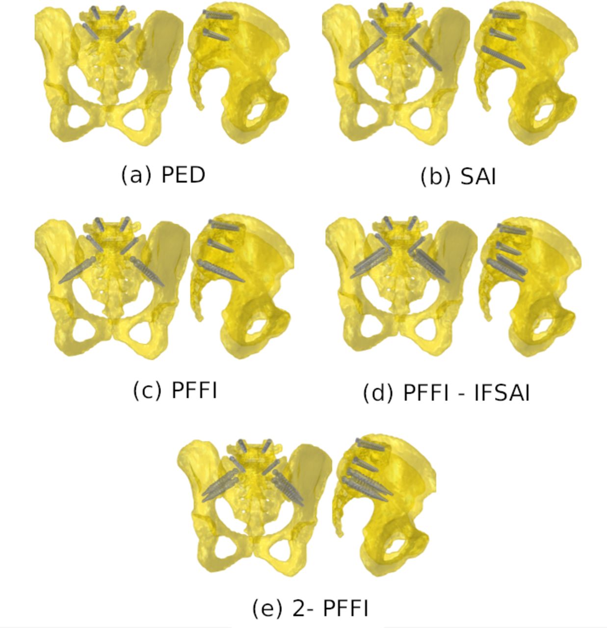
A new PFFI designed to enhance spinopelvic fixation was investigated in this study. Three different sacropelvic fixation configurations were built from the intact model: (1) posterior rods and pedicle screws in the thoracolumbar spine and S1, and PFFI inserted bilaterally in an S2AI trajectory; (2) posterior rods and pedicle screws in the thoracolumbar spine and S1, triangular titanium implants inserted bilaterally in an SAI trajectory, and PFFI inserted bilaterally in an S2AI trajectory (PFFI-IFSAI); (3) posterior rods and pedicle screws in the thoracolumbar spine and S1, PFFI inserted bilaterally in an S2AI trajectory, and PFFI in an SAI trajectory stacked cephalad to those in the S2AI position (2-PFFI; Figure 1). Two configurations developed and described previously24 were used as baselines for comparison with the configurations described in the current study: (1) one configuration with posterior rods and pedicle screws in the thoracolumbar spine and S1 (PED) and (2) the other with posterior rods and pedicle screws in the thoracolumbar spine and S1, and bilateral S2AI screws (S2AI; Table 1, Figure 1).

The five configurations of the instrumentation in the sacropelvic region (left—posterior view of sacropelvis; right—lateral view of sacropelvis): (a) pedicle screw fixation (PED); (b) PED bilaterally supplemented with S2 alar-iliac (S2AI) screws; (c) PED bilaterally supplemented by a porous fusion/fixation implant (PFFI) in an S2AI trajectory; (d) PED bilaterally supplemented with a triangular titanium implant placed in a sacro-alar-iliac trajectory and by a PFFI in an S2AI trajectory (PFFI-IFSAI); (e) PED bilaterally supplemented by a PFFI placed in an S2AI trajectory and a second PFFI in an SAI trajectory stacked cephalad to that in the S2AI position (2-PFFI). Rods are not shown.
Study configurations (refer to Figure 1 for corresponding images).
In all configurations, instrumentation was modeled with representative dimensions. Specifically, pedicle screws had a length of 40 mm and a diameter of 6.5 mm; the posterior rods were modeled, one per side, as beam elements with circular section and had a diameter of 5.5 mm; S2AI screws had a length of 85 mm and a diameter of 8.0 mm; the triangular titanium implants were not connected to the posterior rods and had a length of 50 to 70 mm and an inscribed circular diameter of 7 mm; the PFFI had a length of 85 mm and a diameter of 11.5 mm. The integral porous layer of PFF devices, having an approximate thickness of 0.75 mm and porosity of 60%, was not explicitly modeled. All implants were modeled as having the material properties of titanium (elastic modulus of 110 GPa and Poisson’s ratio of 0.3).
The interaction between pedicle screws (from T10 to L5 vertebra) and thoracolumbar vertebrae consisted of embedded elements (0 relative displacements between the pedicle screws and bone). The interaction between pedicle screws in S1, S2AI screws, triangular titanium implants, and PFFI in the sacrum and ilium consisted of spring elements (simulating the micromovements between the implants and bone). Following the approach described in a previous study,24 2 sets of springs were employed to simulate the interaction for the implants connected to the rods (pedicle screws, S2AI screws, and PFFI): one directed along the main axis of the implant to simulate the pull-out resistance and one with springs connecting nodes on the implant surface with the closest nodes in the surrounding bone tissue to simulate the stiffness in the other directions. For the triangular implants that are not connected with the rods, only the latter set of springs was implemented. The stiffness of the springs was the same for all implants but different among the 2 sets; the 2 stiffness values were calibrated with respect to experimental tests (axial pull-out and torsion) conducted on synthetic bone.24 In order to take into account the differences in bone-implant interaction stiffness among the various implants due to variable size and shape, the spring sets were adjusted so that the number of springs per unit area remained constant for all the modeled implants.
Boundary Conditions and Interactions
All the instrumented models were used to simulate pure moments of 7.5 Nm in flexion, extension, left and right lateral bending, and left and right axial rotation. The moments were applied to the upper endplate of the T10 vertebra through a set of rigid beam elements. Double leg stance was simulated by constraining all nodes belonging to the bilateral acetabula of the finite element models. According to this, 6 simulations for each fixation configuration were run, resulting in a total of 18 simulations.
Model Metrics
A quantitative comparison among the 3 instrumented models was performed relative to the fixation configuration with only pedicle screws (PED) and with S2AI screws. The outputs analyzed in this comparison were as follows: (1) range of motion (ROM) of L5-S1 and SIJ with respect to PED; (2) the maximal von Mises stresses in S1 pedicle screws; (3) the maximal von Mises stresses in either the S2AI screws or in PFFI in an S2AI trajectory; (4) the maximal stresses in the posterior rods between the pedicle screws in L5 and S1 (ie, lumbosacral junction).
Results
ROM, L5-S1, and SI Joints
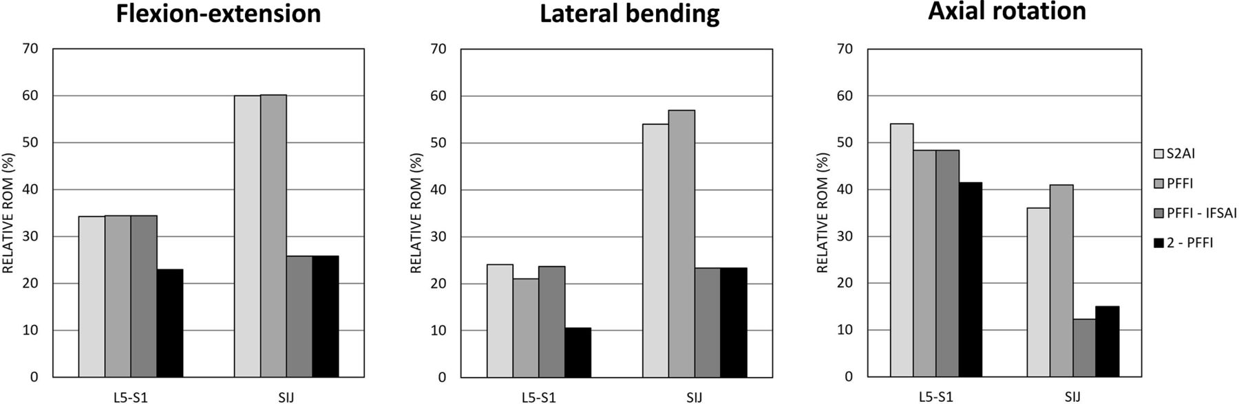
Sacropelvic fixation decreased the relative ROM of L5-S1 and of the SIJ with respect to PED. A similar behavior among S2AI, PFFI, PFFI-IFSAI, and 2-PFFI was found for all 3 loading conditions (Table 2, Figure 2).

Predicted ranges of motion with respect to pedicle screw of L5-S1 and sacroiliac joints in flexion-extension (left), lateral bending (middle), and axial rotation (right) for the 4 instrumented configurations (S2AI, PFFI, PFFI-IFSAI, and 2-PFFI). Refer to Table 1 for model descriptions and abbreviations.
Ranges of motion of L5-S1 and of the SIJ for the various configurations.
At L5-S1, fixation with S2AI showed similar relative ROM as PFFI and PFFI-IFSAI, especially in flexion-extension. In axial rotation, the relative ROM of L5-S1 slightly decreased (<10%) for PFFI and PFFI-IFSAI with respect to S2AI. Adding another PFFI to PFFI (2-PFFI) further decreased the ROM for all 3 loading conditions (Figure 2).
At the SIJ, S2AI demonstrated a decrease in ROM (between 40% and 65%) with respect to PED; similar relative ROM values were noted for PFFI. With regard to S2AI, the largest decrease was found in axial rotation (65%). In this same loading condition, PFFI showed a decrease of 60%. Adding the triangular titanium implant to PFFI (PFFI-IFSAI) further decreased the ROM of the SIJ with respect to the configuration without the triangular implant. The same results found for PFFI-IFSAI were found when a second PFFI was added to PFFI (ie, 2-PFFI). PFFI-IFSAI and 2-PFFI resulted in similar behaviors for all 3 loading conditions: the biggest decrease was found in flexion-extension (35%) with respect to S2AI and PFFI (Figure 2).
Stresses, S1 Pedicle Screws
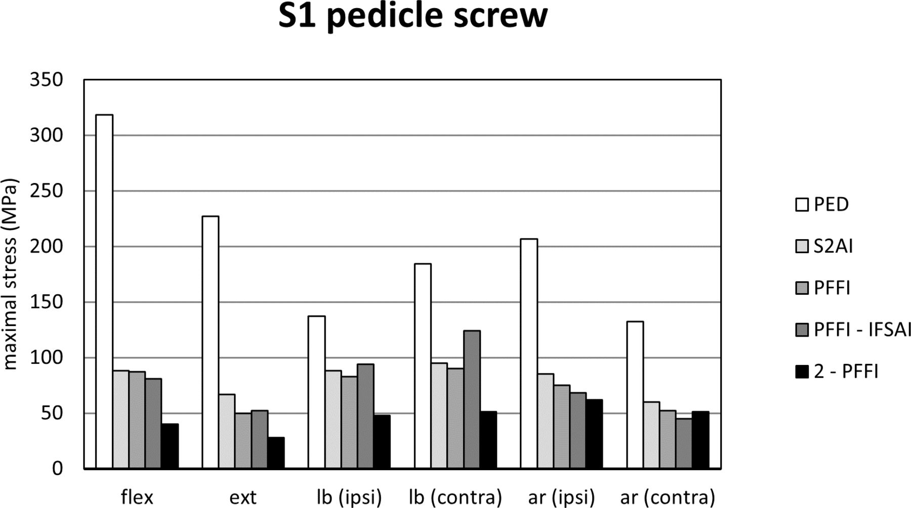
Due to the symmetry in the boundary conditions, the maximal von Mises stresses in the S1 pedicle screws on the right side were similar to those on the left side; thus, only the latter is shown (Figure 3).

Maximal stresses in the left S1 pedicle screw predicted for the 5 instrumented configurations (PED, S2AI, PFFI, PFFI-IFSAI, and 2-PFFI). “flex”: flexion; “ext”: extension; “lb (ipsi)”: lateral bending in the ipsilateral direction (the same side of the implant of interest); “lb (contra)”: lateral bending in the contralateral direction; “ar (ipsi)”: axial rotation in the ipsilateral direction (the same side of the implant of interest); “ar (contra)”: axial rotation in the contralateral direction. Refer to Table 1 for model descriptions and abbreviations.
Compared with PED, the 4 configurations including sacropelvic fixation resulted in lower maximum stresses in the pedicle screws (Figure 3). When an S2AI screw was added to PED, a reduction from 133 to 319 MPa to 60 to 95 MPa was predicted. Adding a PFFI instead of the standard S2AI screw resulted in a reduction from 133 to 319 MPa to 50–90 MPa, demonstrating values similar to S2AI.
Adding a triangular titanium implant to PFFI (ie, PFFI-IFSAI) did not influence the stresses in the S1 pedicle screws with respect to S2AI and PFFI. 2-PFFI resulted in a decrease of the S1 pedicle screw stresses with respect to the other configurations; stresses from 28 to 62 MPa were calculated in this case (Figure 3).
Stresses, S2AI screws, and PFFI
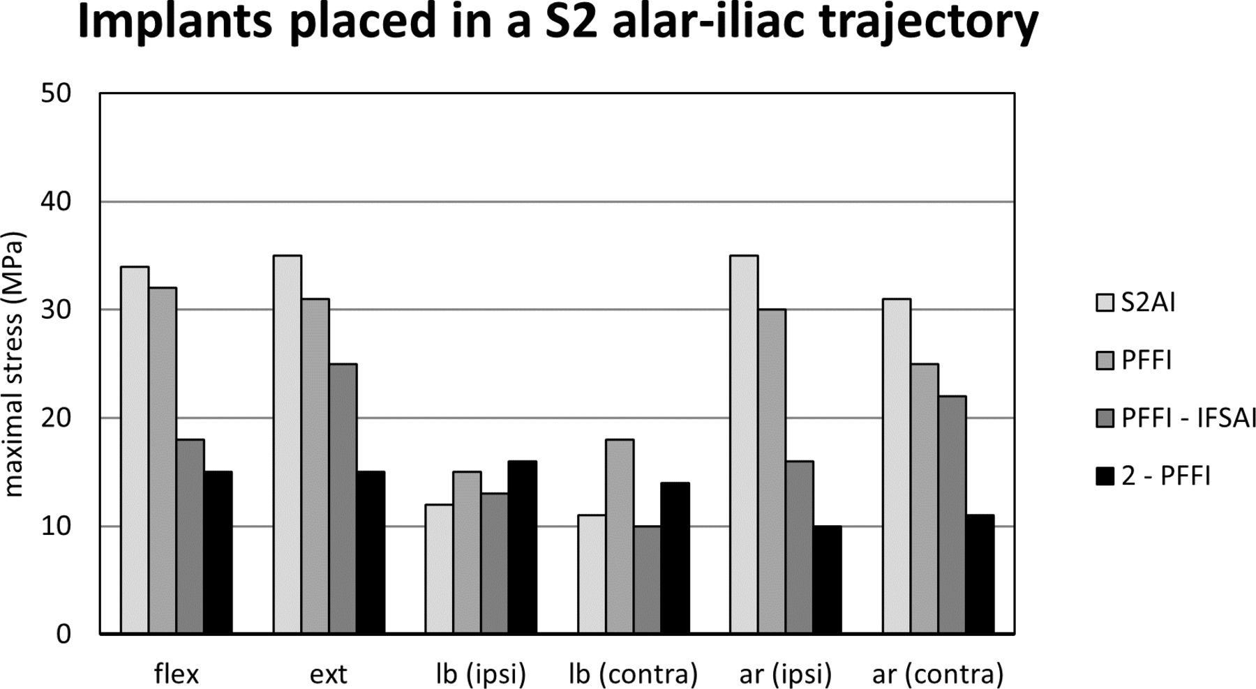
Similar to S1 pedicle screws, the maximal von Mises stresses in S2AI screws and PFFI on the right side were similar to those on the left side; thus, data for the left side is presented (Figure 4). Data is compared among those implants in an S2AI trajectory.

Maximal stresses in the left implants placed in an S2 alar-iliac (S2AI), trajectory predicted for 4 instrumented configurations (S2AI, PFFI, PFFI-IFSAI, and 2-PFFI). “flex”: flexion; “ext”: extension; “lb (ipsi)”: lateral bending in the ipsilateral direction (the same side of the implant of interest); “lb (contra)”: lateral bending in the contralateral direction; “ar (ipsi)”: axial rotation in the ipsilateral direction (the same side of the implant of interest); “ar (contra)”: axial rotation in the contralateral direction. Refer to Table 1 for model descriptions and abbreviations.
In flexion-extension and axial rotation, maximal stresses in S2AI were higher than those in the PFFI. In flexion-extension, PFFI had higher stresses in the PFFI than the PFFI in PFFI-IFSAI and 2-PFFI. PFFI-IFSAI and 2-PFFI had similar stresses with the latter configuration resulting in the smallest stress values among those configurations with PFFI (15 MPa in flexion and 15 MPa in extension). In lateral bending, a similar behavior among PFFI, PFFI-IFSAI, and 2-PFFI was detected. In axial rotation, the configuration 2-PFFI had a protective effect on the maximal stresses observed in the PFFI (up to 66%). Adding the triangular titanium implants (PFFI-IFSAI) also had a protective effect on the maximal stresses observed in the PFFI (up to 50% with respect to PFFI).
With regard to 2-PFFI, maximum stresses in the upper (ie, S1) PFFI were also measured. In flexion-extension, stresses in this implant were similar to those found in PFFI, while in lateral bending, stresses in the S1 PFFI were highest among configurations. In axial rotation, stresses in this PFFI fell between values found for PFFI and PFFI-IFSAI. In all cases, maximum stresses on S2AI screws were found at the portion of the screw crossing the SI joint, whereas stresses in the PFFI were found at the neck.
Stresses and Posterior Rods
As for S1 pedicle screws and S2AI screws, the maximal von Mises stresses in the posterior rods on the right and left sides were comparable due to the symmetry in the boundary conditions; thus, only the stresses on the left side are shown (Figure 5).

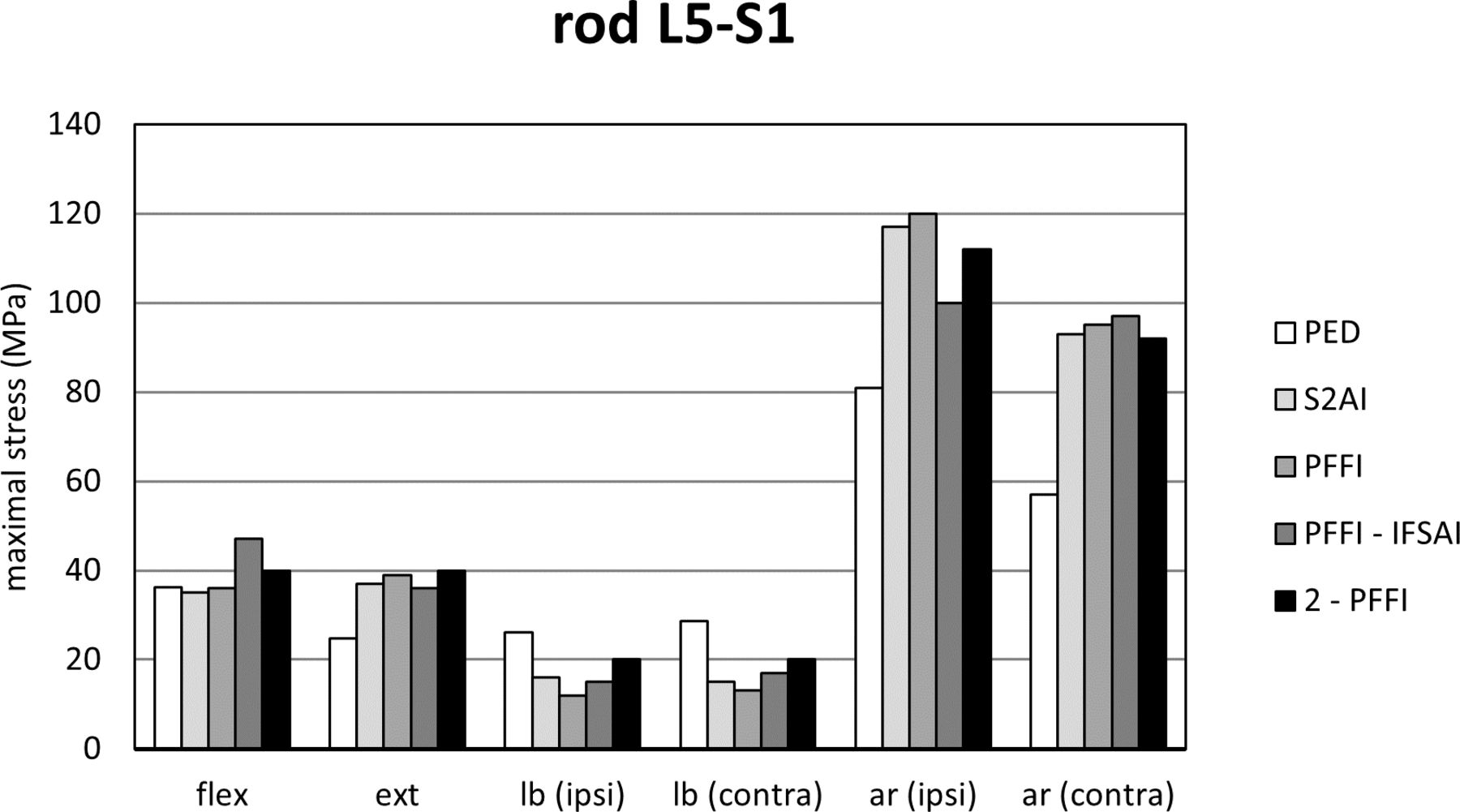
Maximal stresses in the left posterior rods in the portion between the L5 and the S1 pedicle screws (PED) predicted for the 5 instrumented configurations (PED, S2AI, PFFI, PFFI-IFSAI, and 2-PFFI). “flex”: flexion; “ext”: extension; “lb (ipsi)”: lateral bending in the ipsilateral direction (the same side of the implant of interest); “lb (contra)”: lateral bending in the contralateral direction; “ar (ipsi)”: axial rotation in the ipsilateral direction (the same side of the implant of interest); “ar (contra)”: axial rotation in the contralateral direction. Refer to Table 1 for model descriptions and abbreviations.
With respect to simple pedicle screw fixation (PED), adding other implants tended to increase the maximal stresses observed on the posterior rods, except during lateral bending. However, in flexion-extension, the differences of the stresses in the rods were very small. The largest values were found in axial rotation for PFFI (up to 120 MPa). Max stresses in the rods resulted in a similar behavior among S2AI, PFFI, PFFI-IFSAI, and 2-PFFI for all the 3 loading conditions (Figure 5).
Discussion
In this study, the use of a new PFFI to enhance spinopelvic fixation in 3 innovative configurations was investigated by means of finite element models. In the tested configurations, at least one PFFI per side was used in order to compare its biomechanical effect on L5-S1 and SIJ motion, and von Mises stresses in instrumentation with respect to PED and standard sacropelvic fixation with S2AI screws.
Sacropelvic fixation reduced the ROM of both L5-S1 and SIJs for all 3 loading conditions with respect to lumbosacral fixation (PED). The same result was found in other several in vitro or computational studies24–26 in which pedicle screw fixation in the lumbosacral spine alone or supplemented by either IL screws or S2AI screws was tested. The S2AI screws and PFFI had similar results in terms of L5-S1 and SIJ motion. Adding triangular titanium implants to the PFFI did not affect the ROM between L5 and S1 but did reduce that of the SIJ. This finding at L5-S1 is likely due to the fact that the triangular implants are not connected to the rod. Using 2 PFFI per side decreased the motion of the L5-S1 joint as both implants were connected to the rods. This suggests an increase in joint stability as well as a reduced risk of pseudarthrosis of the L5-S1 joint. 2-PFFI demonstrated a behavior similar to PFFI-IFSAI in terms of SIJ motion, which is a reasonable result given that both configurations included 2 implants across the SIJ. Furthermore, these data show that 2 implants across the SIJ further increase the joint’s stability in comparison to a single point of fixation.
As in a previous study, the triangular titanium implants did not have an evident effect on the stability of L5-S1 for all the loading conditions but further reduced the SIJ motion.24,25 Instead, using one PFFI per side showed a behavior similar to the standard S2AI fixation. This is a reasonable outcome given that both configurations include a single implant per side, placed in a similar trajectory, that is connected to the rod and crosses the SI joint. When 2 PFFI per side were used, both L5-S1 and SIJ flexibility decreased with respect to S2AI fixation. Extending the previous rationale for S2AI and PFFI to 2-PFFI, a more pronounced decrease in L5-S1 motion would be expected for the latter configuration as it is a more rigid construct with 2 implants per side connected to the rod and crossing the joint.
Similar to previous studies, sacropelvic fixation significantly reduced the von Mises stresses in S1 pedicle screws..9,24,25,27,28 S2AI fixation showed a slight increase of the stresses on S1 pedicle screws with respect to PFFI. Adding triangular titanium implants to the fixation with a PFFI slightly decreased the stresses in S1 pedicle screws with respect to PFFI, except in lateral bending. 2-PFFI significantly decreased the stresses in this screw with respect to other configurations, except for axial rotation in which the values were very similar among the sacropelvic configurations. The PFFI had, therefore, a moderate protective effect on the S1 pedicle screws suggesting a decreased risk of screw failure.
von Mises stresses in the PFFI placed in an S2AI trajectory or S2AI screws showed that S2AI resulted in higher stresses with respect to PFFI, except in lateral bending. Despite this, lateral bending showed smaller values of stresses with respect to the other 2 loading conditions. Regarding the PFFI in an S2AI trajectory, the configuration with one PFFI, one triangular titanium implant per side, and 2-PFFI resulted in the smallest values of stresses on the PFFI for all 3 loading conditions, in particular for the 2-PFFI. This suggests that the presence of a second implant above that in the S2AI trajectory offers some protection to the latter.
Notably, when a PFFI was placed in an SAI trajectory above the PFFI in an S2AI trajectory (ie, 2-PFFI), stresses in the former were higher than in the latter in all loading conditions, though they were the highest values among all configurations in lateral bending. Generally, this result is unsurprising because stress would be expected to decrease in implants as one travels caudally along the construct. Overall, all stresses in the PFFI were similar to or lower than those found in S1 pedicle screws.
In the posterior rods, the von Mises stresses were found to be comparable for configurations with sacropelvic fixation. Among the configurations with the PFFI, similar values of stresses in the rods were found. The triangular implants did not have an evident effect on the rod stresses, consistent with previous studies.24,25,29 However, all maximum values were lower than the stresses seen in S1 pedicle screws without sacropelvic fixation.
This study does exhibit some limitations, which are also described in previous studies.24,25,29 A simplified loading scenario replicating a double-leg stance in combination with pure moments (ie, no compression) was used. It should be noted that these boundaries and loading conditions were commonly used in in vitro and finite element studies which allows for better comparison among studies.24,25,29–36 While pure moment applications may not be an exact representation of in vivo loading observed in day-to-day activities, previous studies have demonstrated that such loading has produced representative flexibility, intradiscal pressures, and instrumentation strain.31,37–39 Moreover, posterior rods were simulated as beam elements, and kinematic constraints were employed to model tulips because similar approaches are common in the available literature.35,36 The integral porous layer of the PFFI was simplified to accommodate computational run times, likely overestimating the implant bending stiffness; however, modeling of the full trabecular stresses was outside the scope of the current work. Additionally, no interbody fusion at L5-S1 in combination with spinopelvic fixation was employed. Also, as the current study details model behavior at t = 0, the effects of osteointegration afforded by the PFFI are not evaluated here but would be expected to be beneficial compared with non-osseointegrated screws. Furthermore, the work described here considers only the bony properties representative of the CT scans from which the model was built; future studies could investigate the effects of varying bone density on the PFFI stresses (eg, locations and magnitudes). The approach used to model the bone-implant interactions involves assumptions and limitations: (1) the same values of spring stiffness were used for all implants, whereas an implant-specific calibration would have arguably allowed for obtaining more realistic results; (2) axial pull-out and torsion were simulated experimentally to calibrate the springs but bending loads were not. However, the incorporation of the springs as modeled simulates micromotion, which allows for a more representative assessment of joint stability following fixation, and as such, represents an improvement over the use of embedded elements. Finally, the current study investigates ranges of motion and instrumentation stresses as proxies for joint stability and instrumentation failure, respectively, to understand the biomechanics of the sacropelvic fixation methods explored in this work. The authors acknowledge that multiple other clinical factors not captured in this study may play a role in the development of certain phenomena such as pseudarthrosis; thus, clinical investigation would be required to evaluate the applicability of these computational results to patient outcomes. Other technical limitations are reported in detail in our previous finite element studies.24,25,29
Conclusion
In the current study, a biomechanical evaluation of 3 novel sacropelvic fixation techniques using the new PFFI was performed. In general, this finite element study confirmed that the addition of sacropelvic fixation is able to reduce ROM at L5-S1 and lower instrumentation stresses, suggesting a reduced risk of pseudarthrosis at the joint and screw breakage, respectively. Placement of a single PFFI showed similar behavior to S2AI fixation in terms of the motion of the L5-S1 and SI joints; adding another PFFI per side further reduced the motion of these 2 joints demonstrating that the addition of a second point of fixation across the SIJ increases joint stability. Finally, PFFI further decreased the stresses in S1 pedicle screws and those placed in an S2AI trajectory, suggesting a reduced risk of screw failure. Clinical evaluation should be performed to confirm the applicability of results to patient outcomes.
Acknowledgments
The authors thank Francois Follini for providing a 3-dimensional model of the porous fusion/fixation implant for use in this finite element study.
Footnotes
Funding The study was funded by SI-BONE, Inc. and by the Italian Ministry of Health (“Ricerca Corrente”).
Declaration of Conflicting Interests R.D.C. is an employee of and has stock options/stock in SI-BONE, Inc. DPL is an employee of and has stock options/stock in SI-BONE, Inc., and has 3 pending patents and 6 granted patents. A.M. reports as a paid consultant for SI-BONE, Inc. and is a royalties’ bearer. D.W.P. is a paid consultant for SI-BONE, Inc. and is a royalties’ bearer. S.A.Y. is an employee of and has stock options/stock in SI-BONE, Inc., and has 3 pending patents and 6 granted patents. F.G. received funding support for this study from SI-BONE, Inc.
Availability of Data and Material All data are available from the corresponding author upon reasonable request.
- This manuscript is generously published free of charge by ISASS, the International Society for the Advancement of Spine Surgery. Copyright © 2023 ISASS. To see more or order reprints or permissions, see http://ijssurgery.com.
References
In this issue


