


Article Figures & Data
Figures
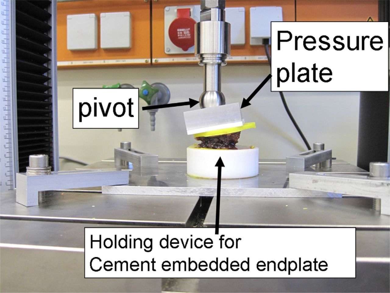
- Fig. 1
Fracture generation. The endplates are embedded in Technovit and placed on a holding device. The length of the sagittal midline is divided into thirds. The center of the pivot is aligned at the transition between the middle and anterior thirds to create vertebral wedge compression fractures (Orthopaedic Trauma Association type A 1.2).
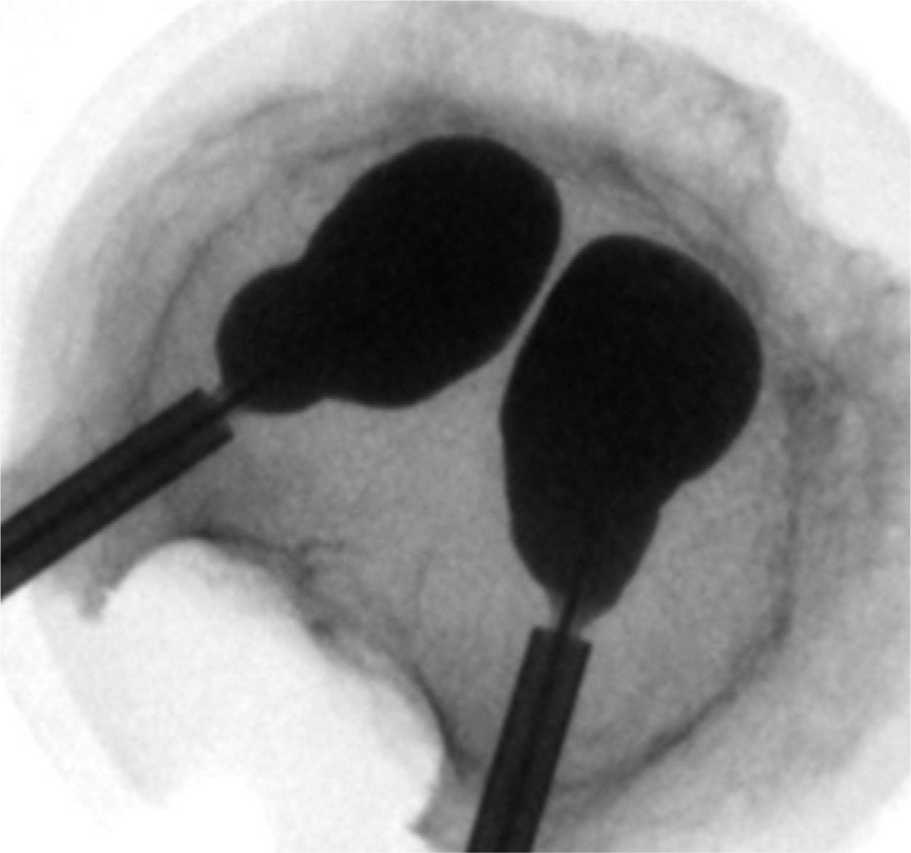
- Fig. 2
Top view of vertebral body with cavity-creating balloons in place (Kyphon).
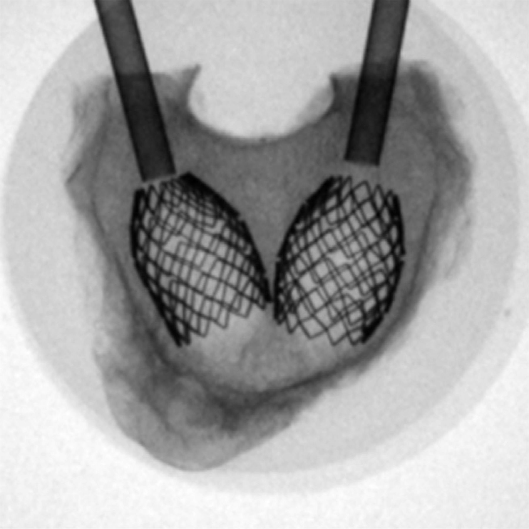
- Fig. 3
Top view of vertebral stents in place. The stents are expanded using a balloon catheter that is removed afterward. The next step would be filling the void with cement (VBS).
- Fig. 4
Top view of RF kyphoplasty. A unipedicular approach is used. High-viscosity cement (StabiliT) is applied after a small cavity has been created.
- Fig. 5
Top view of shield kyphoplasty stent in place. After cavity creation, this covered stent is placed and subsequently filled with cement.
- Fig. 6
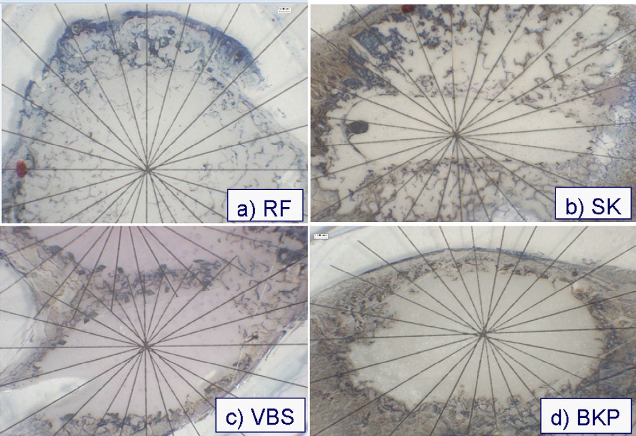
Top view of different cement augmentation techniques. The center of the actinomorphic grid is placed in the center of the cement. (A) RF kyphoplasty (RF). (B) Shield kyphoplasty (SK). (C) Vertebral stenting (VBS). (D) Balloon kyphoplasty (BKP).
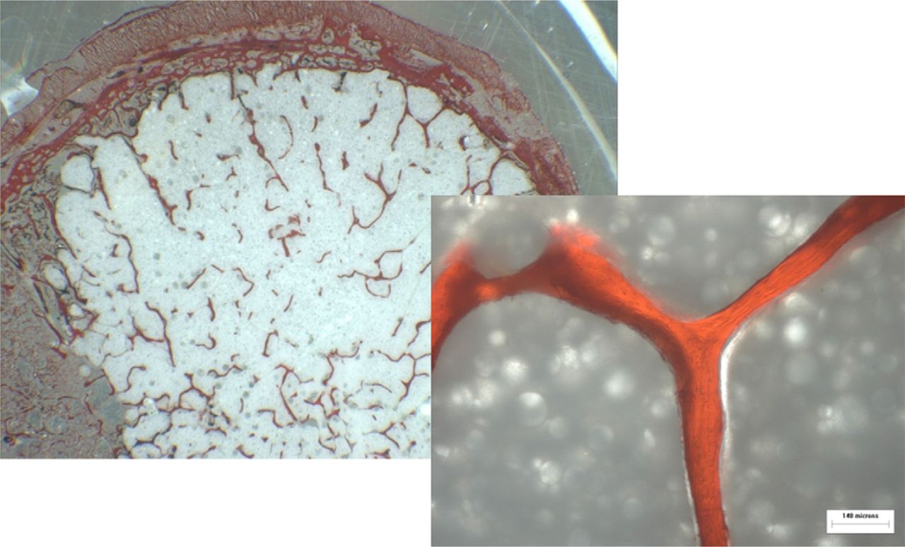
- Fig. 7
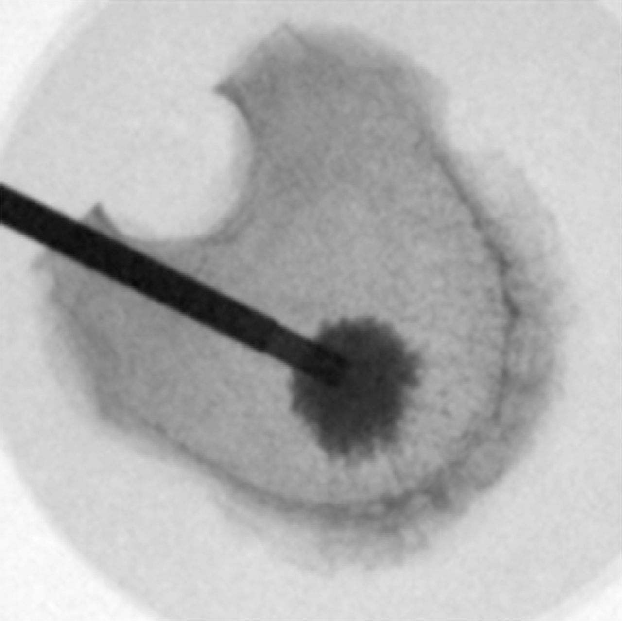
Detailed top view after unspecific staining of cancellous bone (StabiliT RF kyphoplasty). The preserved trabecular structures should be noted.
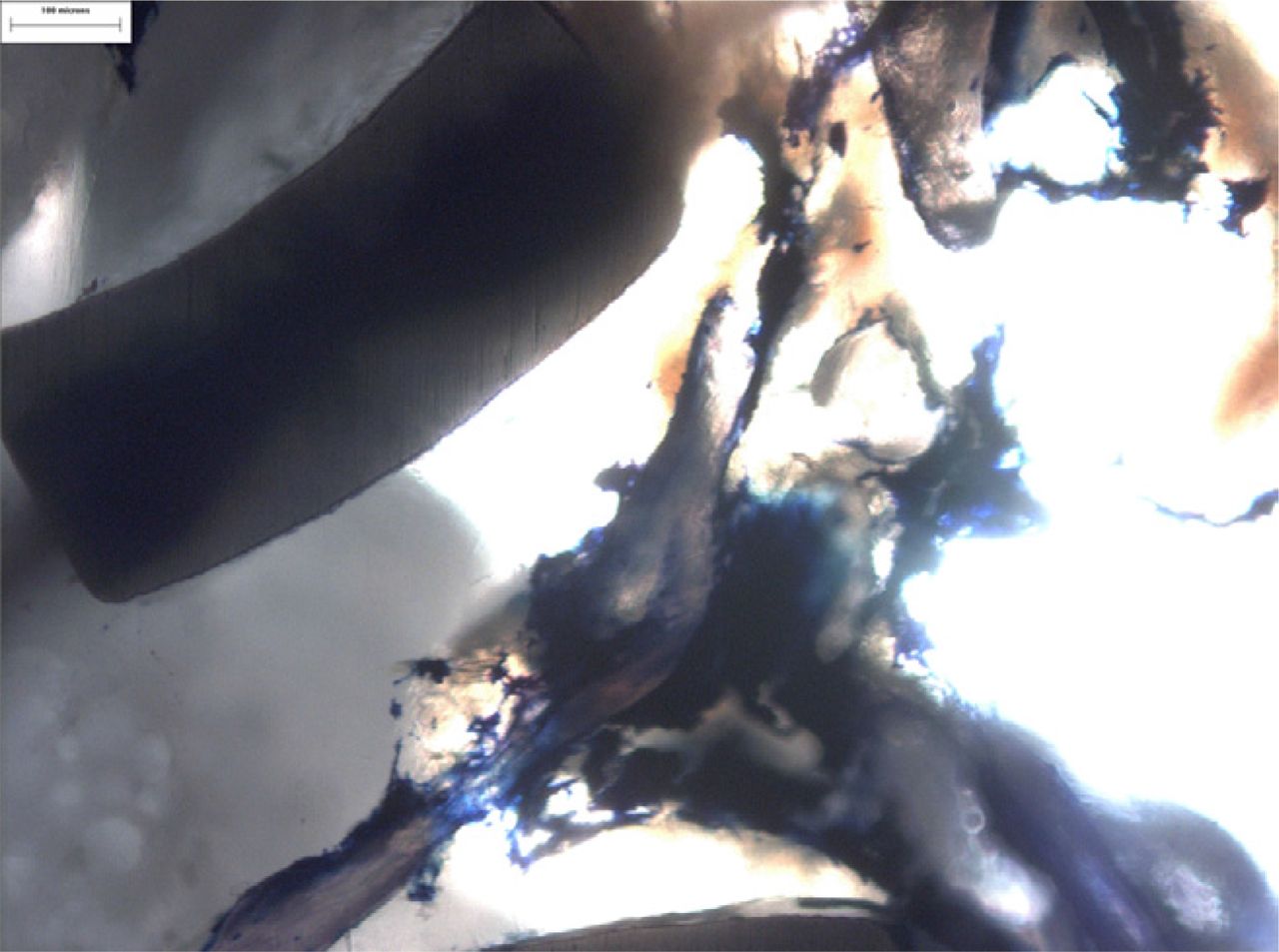
- Fig. 8
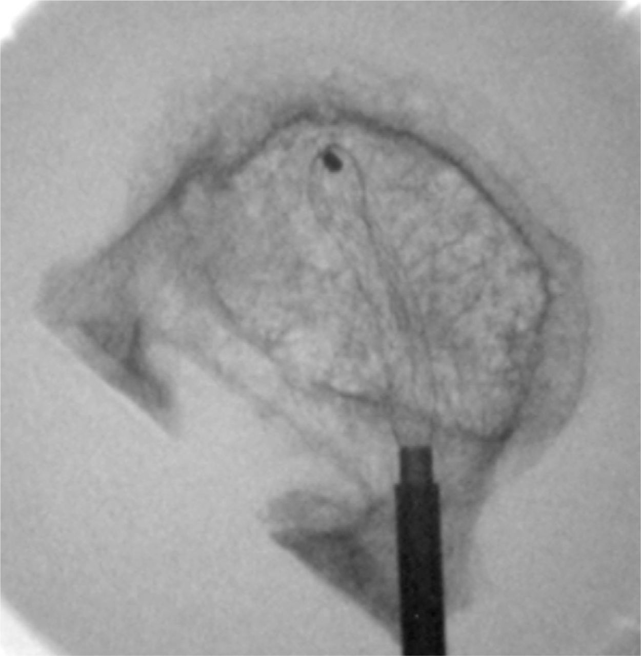
Detailed top view after Giemsa staining (Vertebral Body Stenting [VBS]). The stent, cement, and compressed cancellous bony structures are clearly visible.
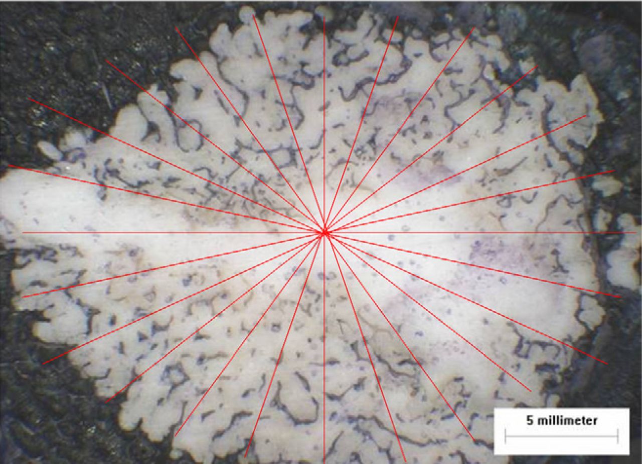
- Fig. 9
Top view of specimen after cement augmentation (StabiliT RF kyphoplasty). From the center of the cement, an actinomorphic grid was placed on the specimens (24 radii, every 15°).
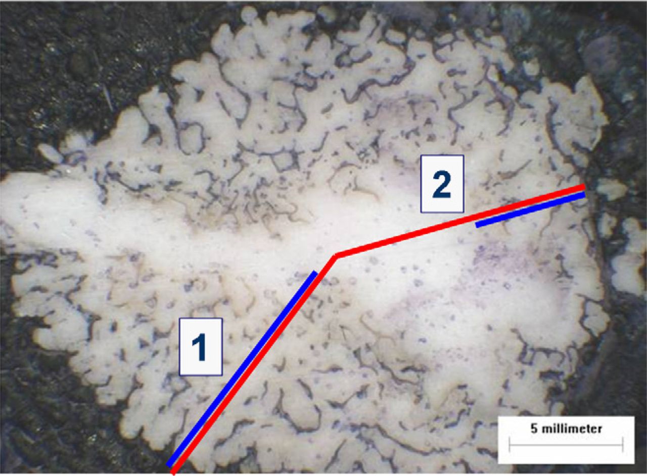
- Fig. 10
To objectify interdigitation, the relation between the length of the radius (center to cement-bone interface [red line]) and preserved trabecular bone along the radius (blue line) was measured for all specimens (1 = 90% and 2 = 45%).
- Fig. 11
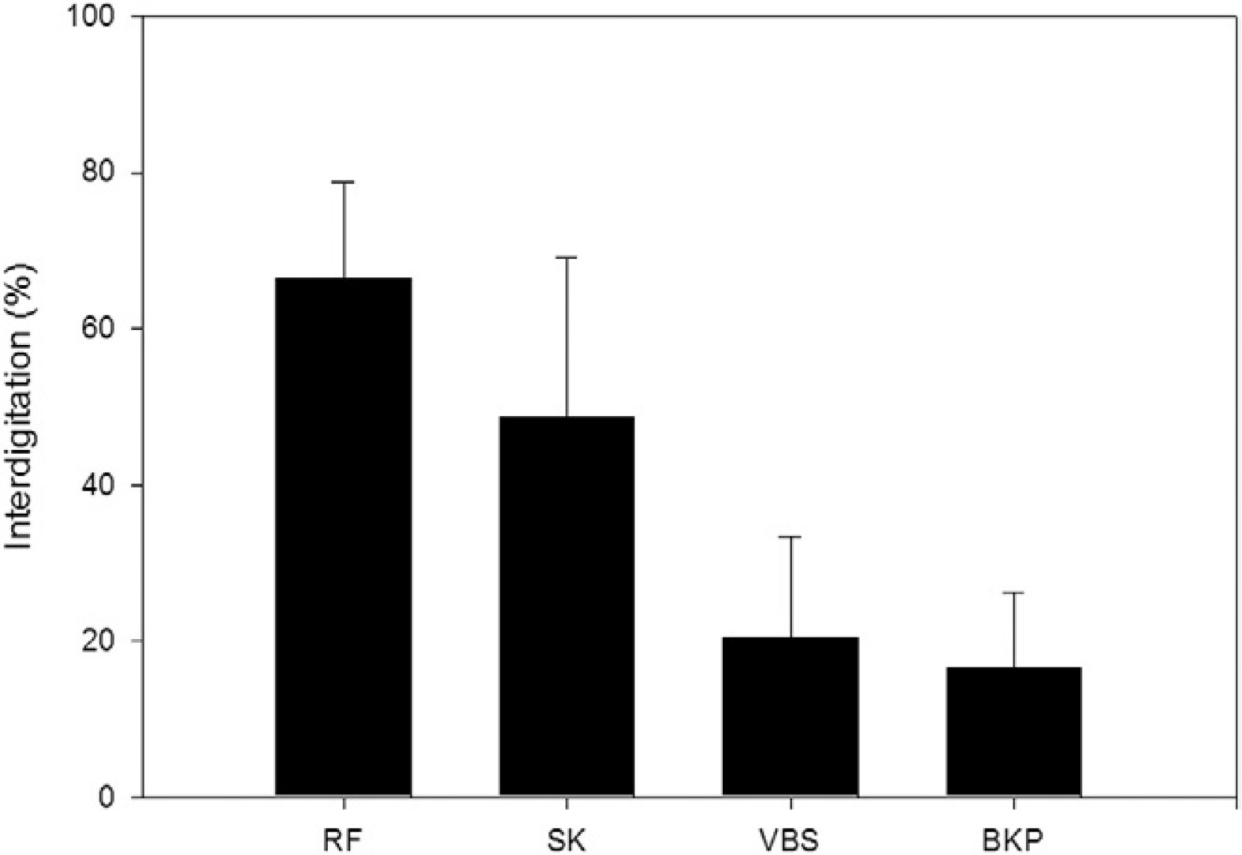
Cement interdigitation of different procedures (mean values and standard deviations). (BKP, balloon kyphoplasty; RF, RF kyphoplasty; SK, shield kyphoplasty; VBS, vertebral stenting.)
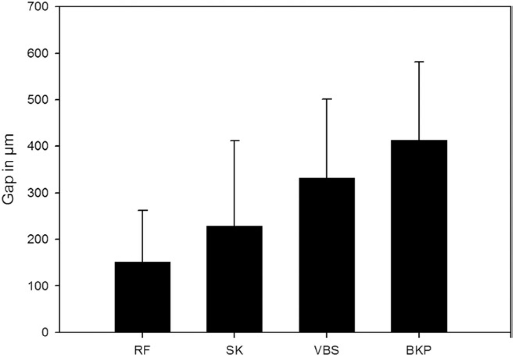
- Fig. 12
Bone-cement interface: gap between outer surface of cement and surrounding cancellous bone in micrometers (mean values and standard deviations). (BKP, balloon kyphoplasty; RF, RF kyphoplasty; SK, shield kyphoplasty; VBS, vertebral stenting.)
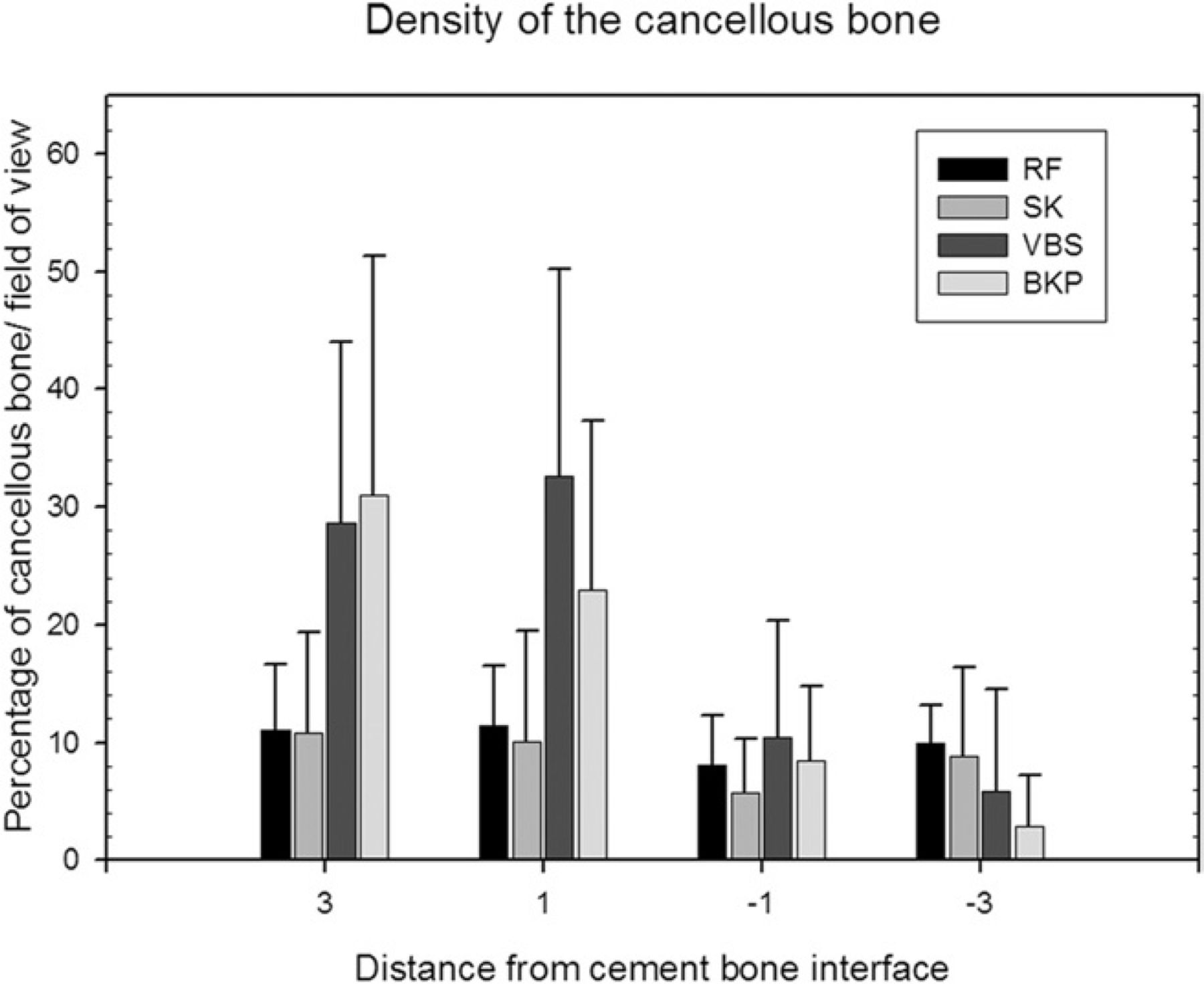
- Fig. 13
Density of cancellous bone at defined distances from cement/bone transition (mean values and standard deviations). Table 2 shows detailed values. (BKP, balloon kyphoplasty; RF, RF kyphoplasty; SK, shield kyphoplasty; VBS, vertebral stenting.)
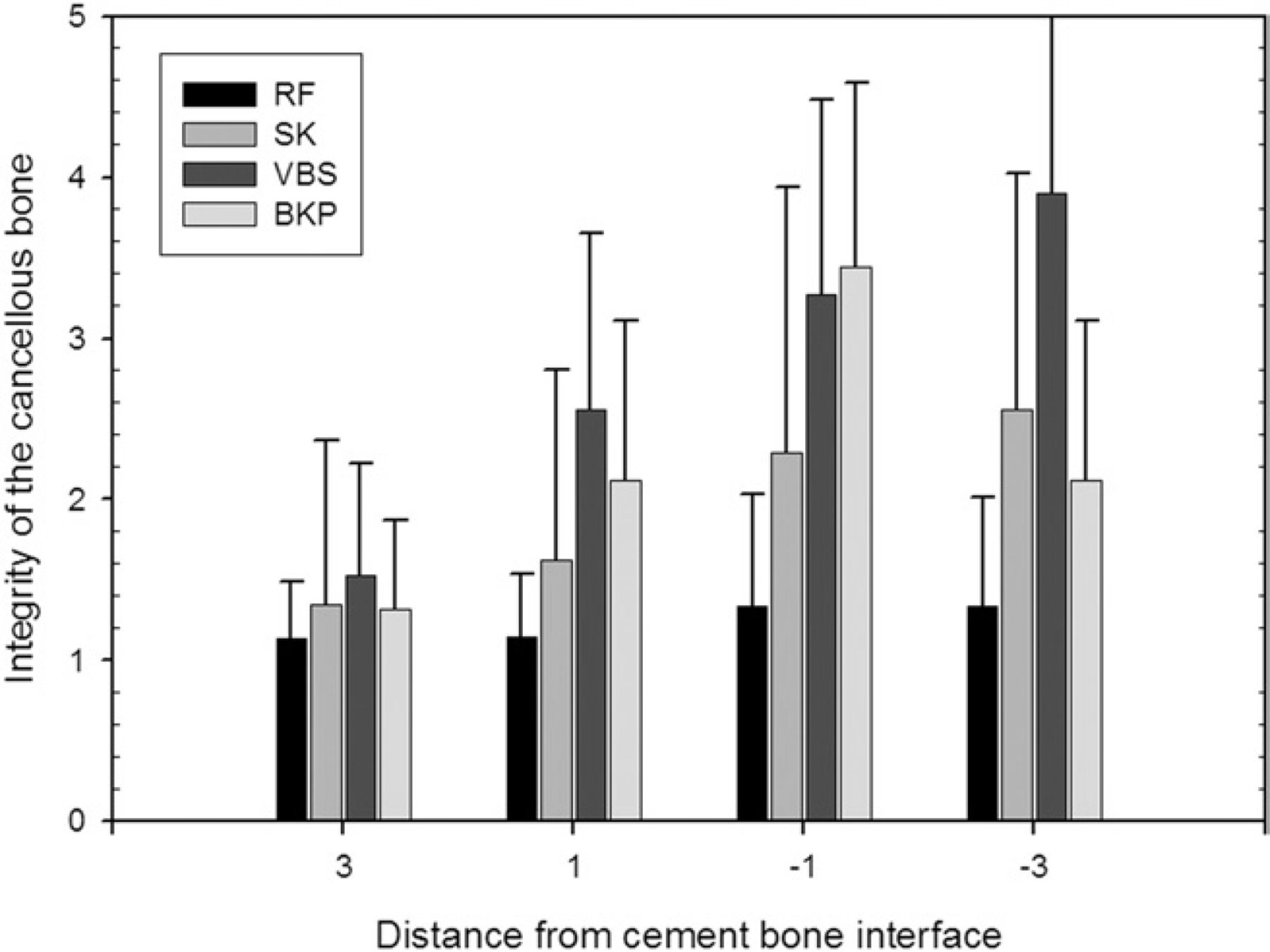
- Fig. 14
Integrity of cancellous bone at defined distances from cement/bone transition (mean values and standard deviations). Table 3 shows detailed values. (BKP, balloon kyphoplasty; RF, RF kyphoplasty; SK, shield kyphoplasty; VBS, vertebral stenting.)


Tables
Value Morphologic characterization of integrity of bony structures 1 Intact bony structures 2 <50% destruction 3 >50% destruction 4 Complete destruction of bony structures 5 No bony structures visible 3 mm from cement-bone interface 1 mm from cement-bone interface −1 mm from cement-bone interface −3 mm from cement-bone interface RF-Kyphoplasty (%) 11.0 (5.6) 11.4 (5.2) 8.1 (4.2) 9.9 (3.2) Shield-Kyphoplasty (%) 10.8 (8.6) 10.1 (9.4) 5.7 (4.6) 8.8 (7.6) VBS (%) 28.6 (15.4) 32.6 (17.5) 10.5 (9.8) 5.9 (8.6) Balloon-Kyphoplasty (%) 31.0 (20.4) 23.0 (14.4) 8.5 (6.3) 2.9 (4.4) Kruskal-Wallis P < .0001 P < .0001 P < .0006 P < .0001 Abbreviation: VBS, vertebral stenting.
NOTE. Data are presented as mean (standard deviation).
3 mm from cement-bone interface 1 mm from cement-bone interface −1 mm from cement-bone interface −3 mm from cement-bone interface RF-Kyphoplasty 1.14 (0.35) 1.14 (0.40) 1.33 (0.70) 1.33 (0.68) Shield-Kyphoplasty 1.35 (1.02) 1.62 (1.19) 2.29 (1.65) 2.56 (1.48) VBS 1.53 (0.69) 2.56 (1.09) 3.27 (1.22) 3.90 (1.13) Balloon-Kyphoplasty 1.32 (0.55) 2.16 (1.00) 3.44 (1.15) 4.32 (0.98) Kruskal-Wallis P < .0005 P < .0001 P < .0001 P < .0001 Abbreviation: VBS, vertebral stenting.
NOTE. Data are presented as mean (standard deviation). Integrity was scored according to the scale in Table 1.
In this issue


