


Article Figures & Data
Figures
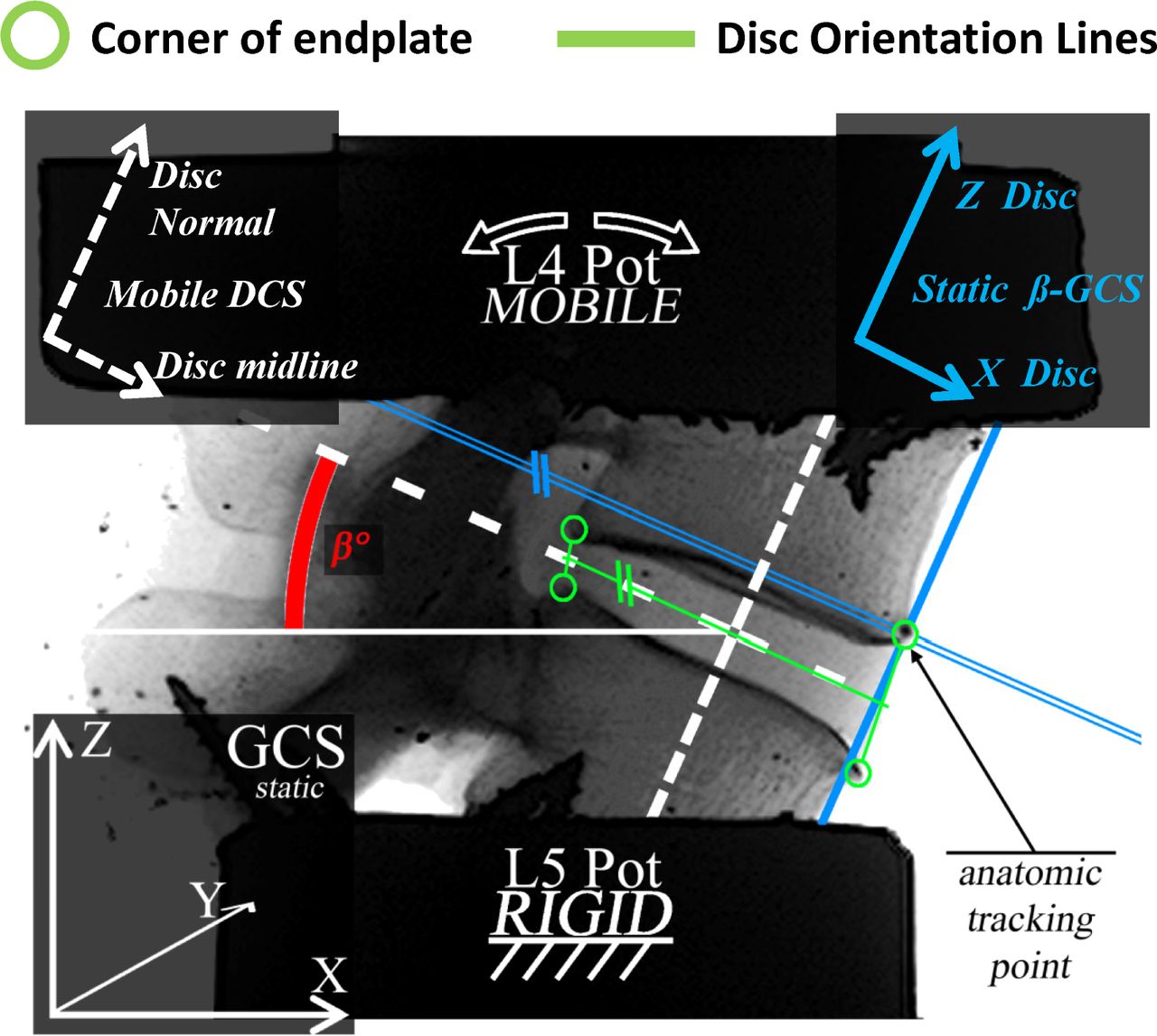
- Fig. 1
Potted L4-L5 Specimen Parameters. Anterior and posterior corners of the cranial and caudal endplates (circled in green) were used to determine the midline of the intervertebral disc with inclination angle β to the global coordinate system (GCS) horizontal. A moving disc coordinate system (DCS) was used to establish the dynamic orientation of the midline of the intervertebral disc during testing. Anterior-posterior and cranial-caudal displacements of the anterior corner of the L4 endplate were determined within a fixed global coordinate system (β-GCS) aligned with the midline of the intervertebral disc and with origin at the L4 endplate corner under zero load conditions.
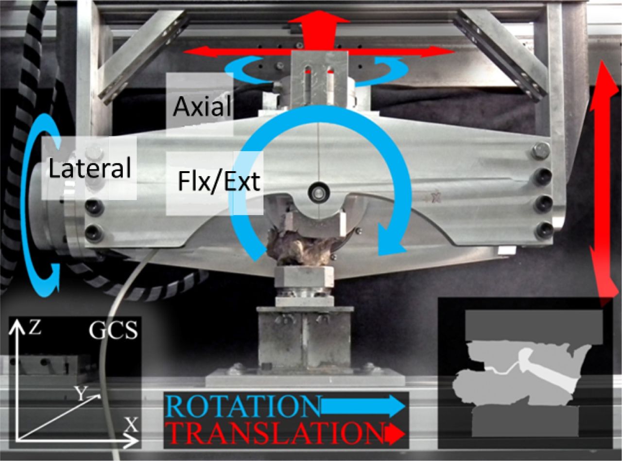
- Fig. 2
Robotic Cartesian Biomechanical Testing System with L4-L5 Specimen. Three orthogonally oriented translational axes (red arrows) established a global Cartesian coordinate system (GCS) (left) with suspended gimbal comprised of three orthogonally oriented rotary motors (blue arrows). A six-axis force-moment sensor (FMS) was rigidly attached between the mobile end of the gantry system and cranial surface of the L4 specimen pot. All loads were commanded and controlled within a local moving force-moment sensor coordinate system (FMS-CS) the orientation of which was determined by the position of the gimbal motors.
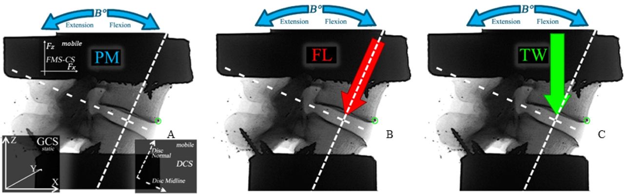
- Fig. 3
Schematic Illustration of Applied Load Conditions. The loading conditions applied to each test specimen in the current study were A) sagittal plane pure moments (PM); B) simulated follower load (FL) protocol comprised of a 400N force maintained in a direction normal to the midline of the intervertebral disc in combination with sagittal plane pure moments; C) a novel trunk weight (TW) loading protocol comprised of constant vertically oriented 400N force in combination with sagittal plane pure moments. A) also illustrates the initial orientations of the force-moment sensor (FMS-CS) and disc (DCS) coordinate systems.
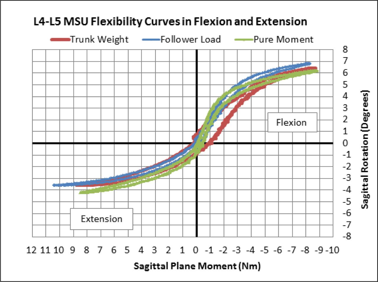
- Fig. 4
Flexibility Curves for Single Test Specimen. Flexibility profiles for a single specimen tested under pure moment, follower load and trunk weight loading protocols. All three protocols exhibited typical non-linear hysteresis characteristics.
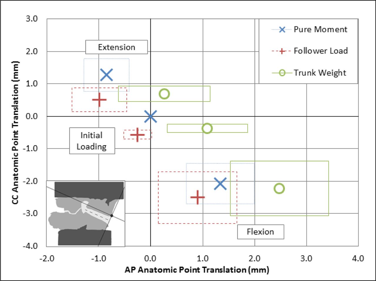
- Fig. 5
Mean values of anterior-posterior (AP) (X axis) and cranial-caudal (CC) (Z axis) anatomic tracking point displacements in the β-Global Coordinate System are presented for the PM, FL and TW protocols in three groupings indicating values at 8 Nm of extension (top-left quadrant), 0 Nm neutral position (origin), and at 8 Nm of flexion (bottom right quadrant). Boxes represent one standard deviation from the mean value in both AP and CC directions.
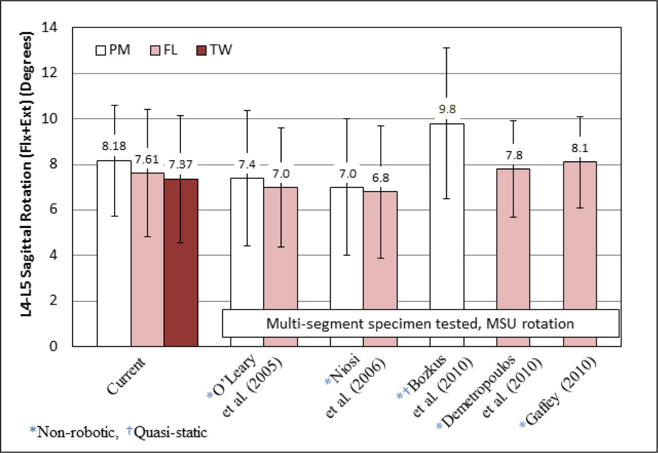
- Fig. 6
Combined Sagittal Rotational Range of Motion Literature Comparison. Mean sagittal plane L4-L5 MSU rotational ranges of motion in flexion and extension were combined for presentation and comparison with previously published values of combined L4-L5 ranges of motion. Differences between studies such as single versus multi-segment specimens, non-robotic versus robotic and continuous versus quasi-static loading methods are noted.


Tables
Bending Region Displacement Direction Loading Protocol Mean Displacement (mm) SD Statistical Differences Neutral1 PM 0.0 ± 0.0 TW: p = 0.005* AP FL -0.2 ± 0.3 TW: p = 0.001* TW 1.1 ± 0.7 PM, FL PM 0.0 ± 0.0 FL: p < 0.0001*, TW: p = 0.0001* CC FL -0.6 ± 0.2 TW: p = 0.017* TW -0.4 ± 0.2 PM, FL Extension2 PM -0.8 ± 0.4 TW: p = 0.0008* AP FL -1.0 ± 0.6 TW: p = 0.0003* TW 0.3 ± 0.9 PM, FL PM 1.2 ± 0.5 FL: p = 0.0022* TW: p = 0.014* CC FL 0.6 ± 0.4 PM TW 0.7 ± 0.3 PM Flexion3 PM 1.3 ± 0.7 TW: p = 0.001* AP FL 0.9 ± 0.8 TW: p < 0.0001* TW 2.5 ± 0.9 PM, FL PM -2.0 ± 0.7 FL: p = 0.0052* CC FL -2.5 ± 0.9 PM TW -2.3 ± 0.8 FL: p = 0.058 Mean anterior-posterior (AP) and cranial-caudal (CC) anatomic tracking point (anterior corner of the L4 end plate) displacements with respect to the β-global coordinate system are tabularized for each of the three loading protocols in the neutral (0Nm bending), fully extended (8Nm) and fully flexed (8Nm) positions. Significant differences are indicated in the last column.
↵* Statistically significant 0.05 CI.
In this issue


Jump to section
Related Articles
Cited By...
- No citing articles found.