


Article Figures & Data
Figures
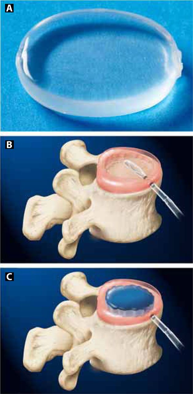
- Figure 1
The DASCOR device (A) is formed by inserting a balloon catheter into the prepared nuclectomy space (B) and injecting liquid polyurethane under pressure which cures in situ (C) within minutes to form the final device.
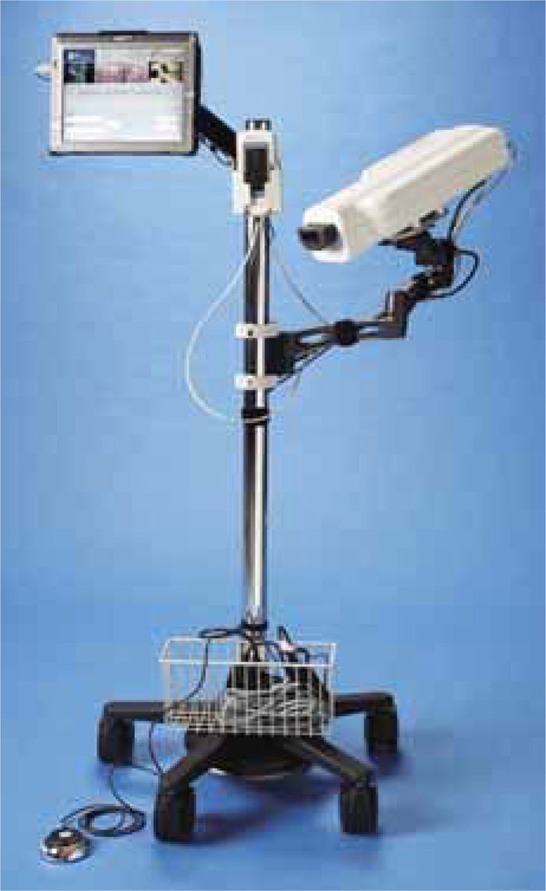
- Figure 2
The software-controlled and tablet PC-monitored injection system used to implant the DASCOR device.
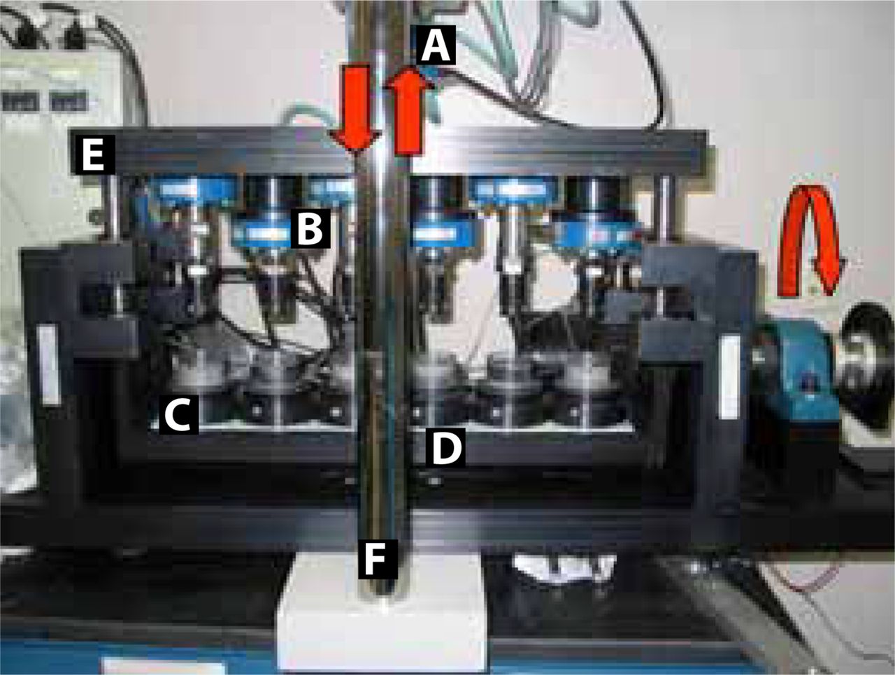
- Figure 3
The six-station custom wear testing apparatus used to conduct all the fatigue testing reported in this study. (A) The main load cell used to measure the total compressive load across all six stations. (B) The load cell used to measure the loads in each test station. (C) The bottom test station assembly used to mount a lower platen as well as the heater used to maintain test station fluids at 37°C. (D) The lower platform of the testing machine, which has the capability to rotate about its longitudinal axis. (E) The upper platform, which is attached to the actuator of the servo-pneumatic material testing machine. (F) The frame of the servo-pneumatic materials testing machine (Smart Test series SP 12600, Bose Corporation, Eden Prairie, Minnesota).
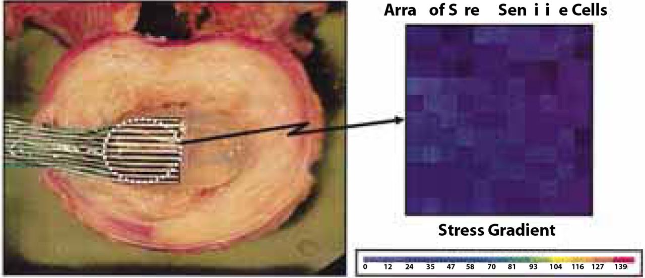
- Figure 4
A typical example illustrating the placement of the stress sensor transducer (K-Scan System, Tekscan Inc, Boston, MA) between the DASCOR device and adjacent endplate (stress sensor is retracted backwards to show the device). Quantitative stress measurements are obtained from the array of sensing elements by assigning a color gradient with a small range of stress magnitudes. Stress uniformity is therefore measured by examining the variation of color gradients.
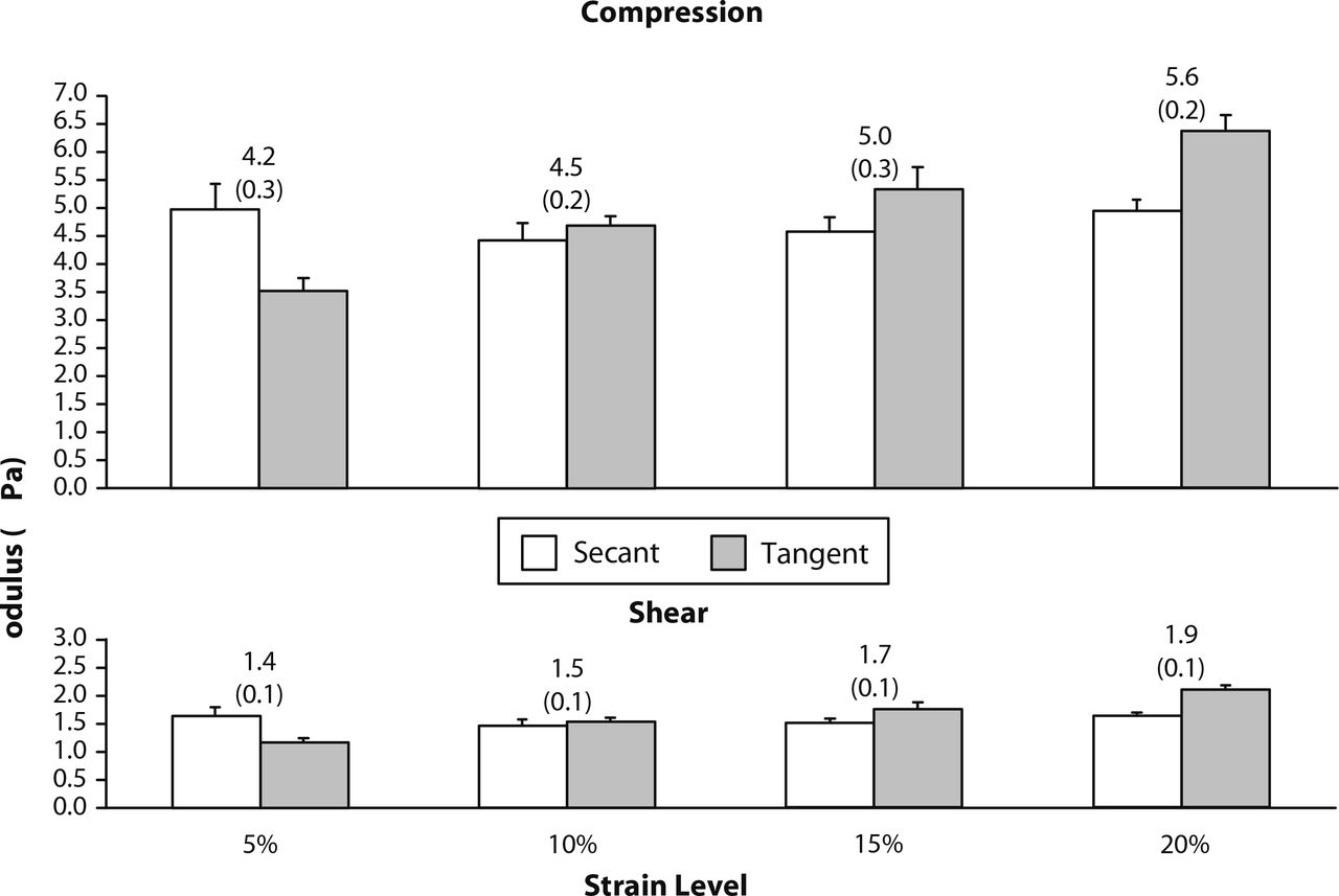
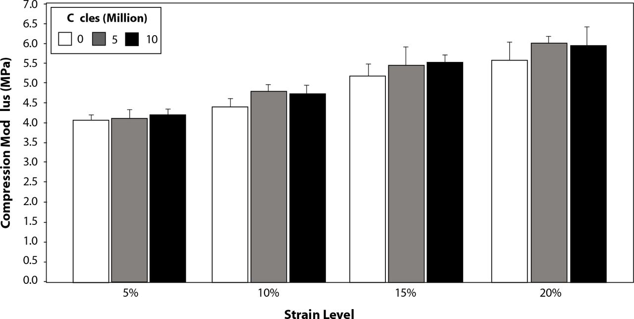
- Figure 5
Compression and Shear Properties
Mean compression and shear moduli at different compressive strains obtained using the secant and tangent methods of modulus calculation. Values between bars denote the averaged value of modulus for a particular strain level. Values in parentheses and error bars denote one standard deviation.
- Figure 6
A plot of stress versus the number of cycles to failure (S/N) depicts the axial compressive fatigue strength of the DASCOR device (ie, ability to withstand 10 million cycles without failure). The mean axial compressive stress applied and the resulting number of cycles to failure for each tested sample is tabulated. The legend within the plot describes the axial compressive load (in newtons) of each sample tested.
Note: FF: Samples that experienced a functional failure, defined as the first appearance of a crack in the polyurethane core; CF: Samples that experienced a clinical failure, defined as the detachment of the balloon from the polyurethane core, without exhibiting the characteristics of a functional failure; Runout: Samples able to withstand 10 million cycles without failure.
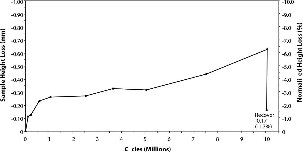
- Figure 7
A plot illustrating the mean sample height loss (also normalized to intact height) experienced during the fatigue testing conducted to characterize the wear and durability of DASCOR samples. Residual height loss after sample recovery was defined as the permanent set.
- Figure 8
The mean compression modulus measured for DASCOR samples that underwent mechanical durability and wear assessment. Each compression modulus reported is a mean value obtained between the tangent and secant modulus measured for each strain level reported.
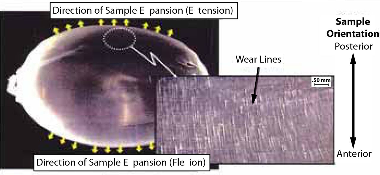
- Figure 9
A depiction of the wear location that occurred on the DASCOR balloon on samples tested for mechanical durability and wear assessment. The small yellow arrows denote the direction of the sample's maximal radial expansion during cyclic flexion and extension movements. A magnified view of the peripheral sample area most radial with respect to the center of the DASCOR samples showed evidence of minor wear line scratches, minor pitting, and deposition of wear particles, all consistent with the direction of radial expansion during wear testing. The latter sample location also experienced the highest total stress when compared to central sample locations (ie, bending stresses were highest most distally to the major diameter and nearly zero along the major diameter).
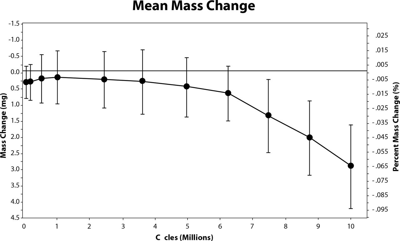
- Figure 10
A plot of the mean mass change versus the number of flexion/ extension cycles for all DASCOR samples that underwent mechanical durability and wear assessment. The y axis on the right also provides a scale which normalizes the mass change as a function of the mean initial sample mass. Error bars reflect one standard deviation.
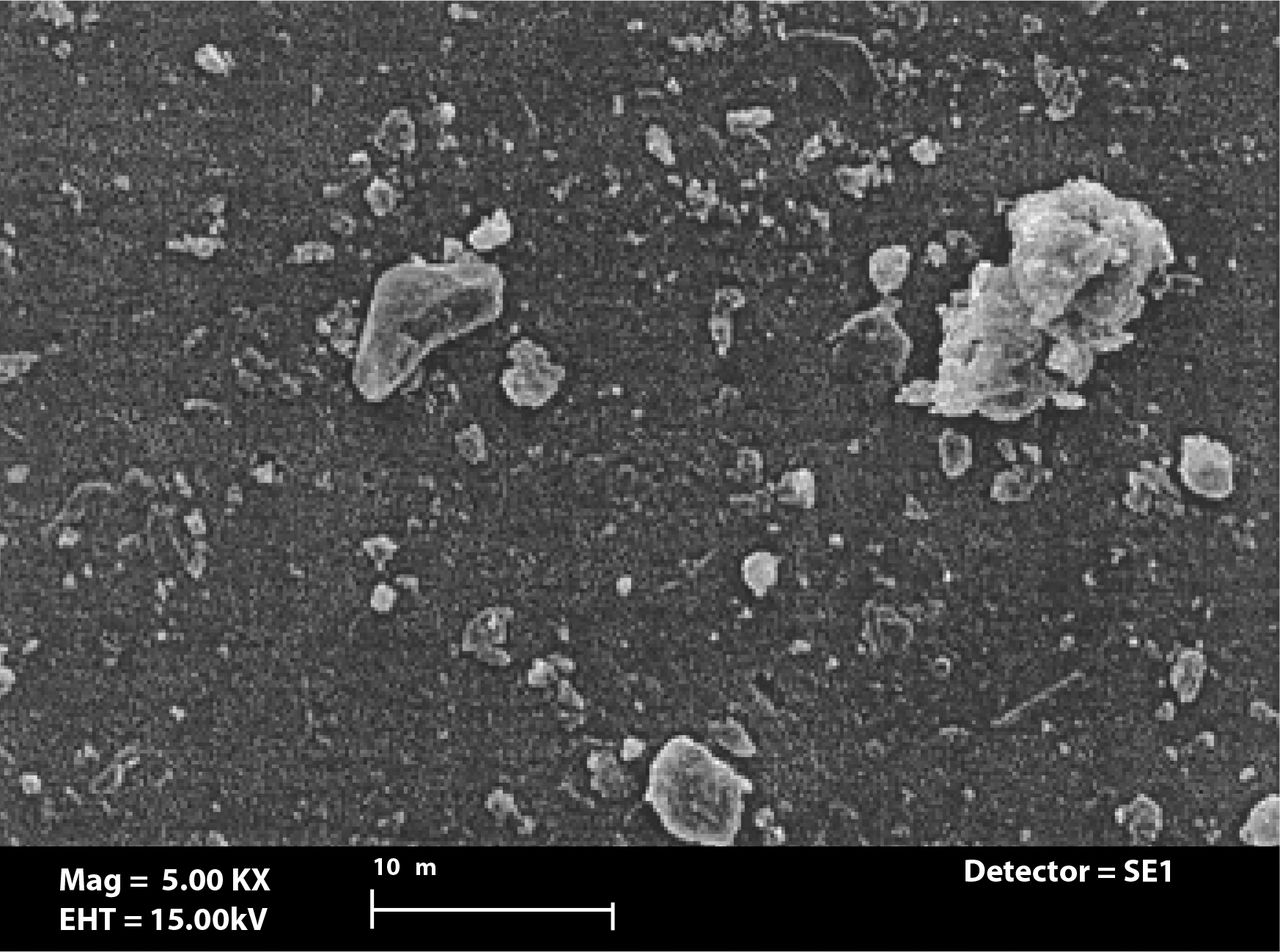
- Figure 11
A scanning electron micrograph of typical particles observed in sample solutions used for particle characterization.
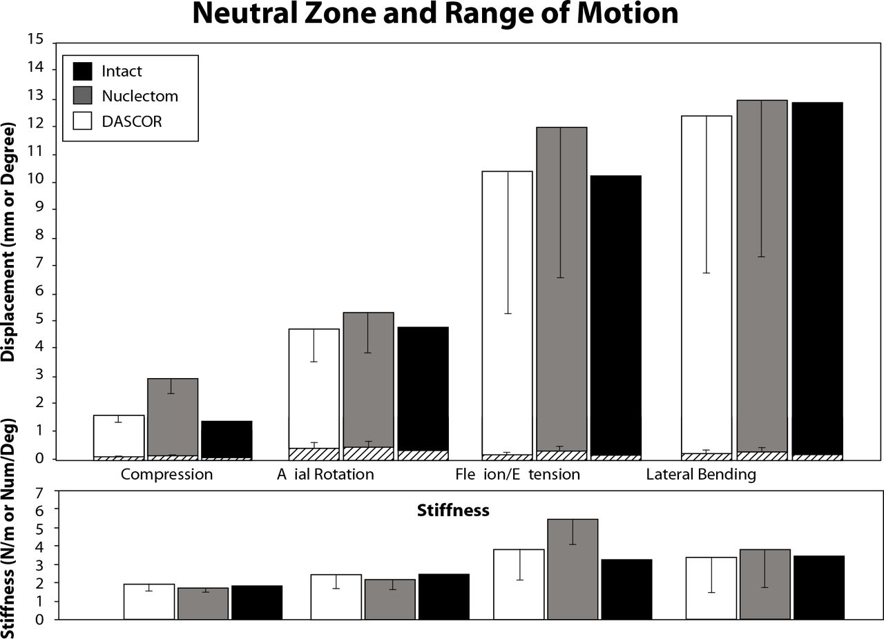
- Figure 12
A figure depicting the multidirectional flexibility results comparing the intact, nuclectomy, and nucleus replacement device segmental constructs. The graph on top presents the results obtained for neutral zone (crossed line bars within solid shaded bars) and range of motion. The bottom graph presents results obtained for segmental stiffness. Error bars reflect one standard deviation.
- Figure 13
A figure depicting the multidirectional flexibility results comparing the intact, water balloon and nucleus replacement device segmental constructs. The graph on top presents the results obtained for neutral zone (crossed line bars within solid shaded bars) and range of motion. The bottom graph presents results obtained for segmental stiffness. Error bars reflect one standard deviation.


Tables
- Table 1
Particle Shape Descriptor Cycles (Millions) 0 0.5 2.5 5 6.25 7.5† 10† Equivalent Circle Diameter(µm) 1.22 (0.74) 1.34 (0.92) 1.55 (1.51) 1.36 (0.89) 1.17 (1.21) 1.69 (3.62) 1.04 (1.75) Aspect Ratio 1.45 (0.32) 1.45 (0.34) 1.54 (0.46) 1.51 (0.43) 1.42 (0.45) 1.33 (0.22) 1.35 (0.26) Elongation 1.74 (0.61) 1.73 (0.63) 1.93 (0.81) 1.85 (0.88) 1.63 (0.78) 1.51 (0.45) 1.51 (0.51) Roundness 0.74 (0.13) 0.75 (0.13) 0.71 (0.15) 0.72 (0.14) 0.82 (0.16) 0.83 (0.13) 0.83 (0.13) Form Factor 0.88 (0.07) 0.88 (0.08) 0.85 (0.10) 0.87 (0.09) 0.92 (0.09) 0.93 (0.07) 0.93 (0.08) Mean particle shape characteristics as defined by ASTM F1877 using SEM visual inspection. Particle shape descriptors in cycle time points denoted with an “†” were significantly different than the rest (P < .05). Values in parentheses denote one standard deviation.
- Table 2
Loading Condition Contact Stress (MPa) Water Balloon DASCOR® Difference Compression 0.94 (0.19) 0.80 (0.06) 0.16 (0.19) Axial Rotation 0.32 (0.09) 0.21 (0.02) 0.10 (0.08) Flexion 0.71 (0.28) 0.56 (0.14) 0.10 (0.16) Extension 0.51 (0.23) 0.44 (0.08) 0.12 (0.16) Lateral Bending 0.49 (0.26) 0.39 (0.09) 0.15 (0.15) The mean contact stress measured at the interface between the implant and the lower endplate during multi-directional segmental flexibility testing. The mean difference in contact stress between the two implant constructs tested is denoted in italics. Values in parentheses denote one standard deviation.
In this issue


Jump to section
Related Articles
Cited By...
- No citing articles found.