

Article Figures & Data
Figures
- Figure 1
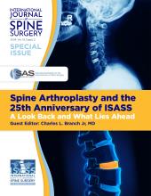
(A) Photo of the checklist printed prior to each case ensures that all items, instruments, and equipment are available. (B) The electronic version of the checklist that can be used on a computer, tablet, or handheld device. The electronic checklist moves checked items to the bottom of each sublist, making missing equipment obvious at the top of the sublist. Furthermore, the electronic version contains pictures of key items, along with notes, storage, and ordering information. These are modified and optimized on an ongoing basis by each surgical team. Checklists are available at https://bhanimd.com/master-checklist-home.
- Figure 2
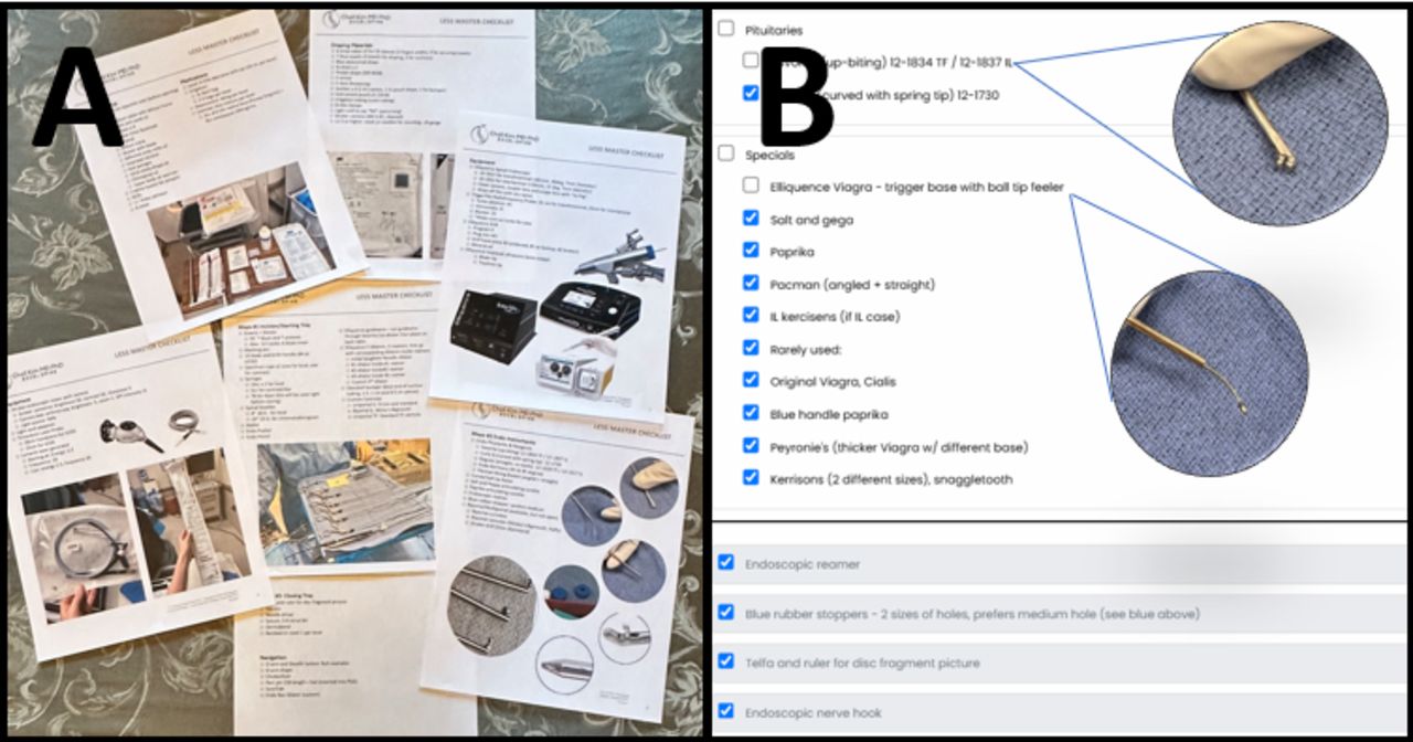
(A) Schematic stick figure diagram of root setup. (B and C) Electronic version of room setup for use on a computer, tablet, or handheld device. The electronic room setup diagram is interactive, allowing for viewing in multiple angles and zooming in and out. The virtual model is available at https://bhanimd.com/room-setup.
- Figure 3
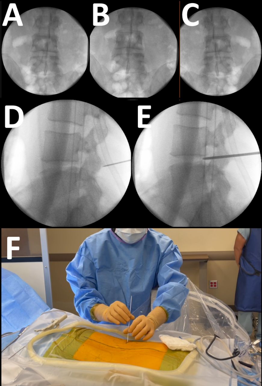
Intraoperative anteroposterior (AP) C-arm image to find the “perfect AP.” The AP view is obtained for each level of surgery. The perfect AP view is obtained with the C-arm straight up, perpendicular to the floor. The patient is then rotated on the bed until the best AP image can be obtained. The perfect AP view is actually the “least imperfect” view, which is obtained by rotating the bed back and forth from imperfect (A), to perfect (B), then beyond to imperfect again (C), then back to perfect (B). The patient is now square relative to the floor. The C-arm is then brought under the table, parallel to the floor, for a lateral view. Wagging the C-arm side to side then aligns the endplates and pedicles. Again, the least imperfect view is chosen. With the best lateral image, the spinal needle is used to anesthetize the surgical corridor, including the lateral aspect of the facet joint (D). The needle also serves to fine-tune the location of the incision for optimal trajectory of the initial dilator (E). Depending on the pathology to be addressed, the transforaminal approach is usually 10 to 15 cm from the midline about 2 to 3 cm cephalad to the disc space line. The initial dilator lands on the facet joint, which is then walked down the superior articular process (F). The intertransverse membrane is then penetrated using a controlled back-and-forth twisting motion. A release can usually be appreciated.
- Figure 4
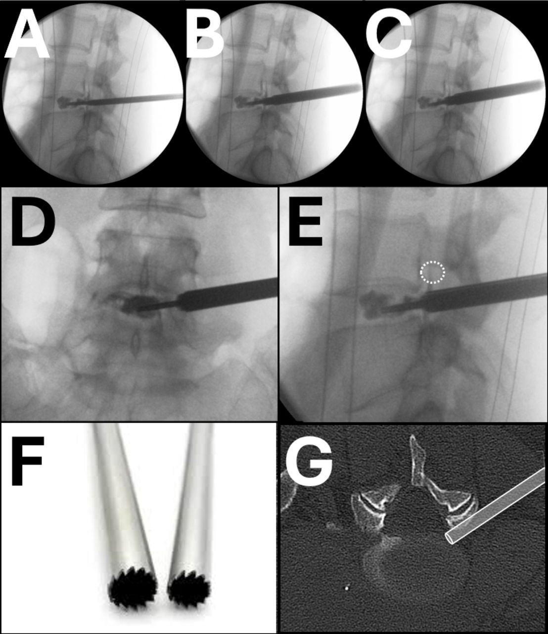
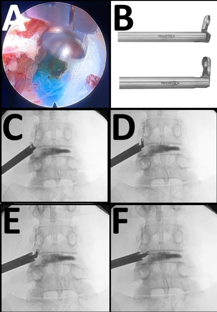
The initial dilator should be lateral to the medial border of the pedicle on anteroposterior (AP) imaging (A), at the posterior vertebral body line on the lateral image (B), and angulated slightly cephalad to caudad, which allows the initial dilator to enter the neuroforamen from a more medially. The tip is then directed to Kambin’s triangle, bordered laterally by the exiting nerve root and medially by the traversing nerve root (C).2 The initial dilator is then wanded back and forth to palpate and clear the disc. A long 22-gauge spinal needle is then inserted through the initial dilator and into the nucleus of the disc. A chromatodiscograph is performed using a combination of dye (either methylene blue or Indigo Carmine) and preservative-free contrast media. The C-arm is kept in the lateral position, and serial images are obtained to outline the annular defect (D, E, and F). The injection is halted when contrast media can be seen leaking posteriorly (F).
- Figure 5
The initial dilator is tamped into the disc and used as an anchor for the dilation and reaming. Sequential dilators and reamers are used to expand the surgical corridor. Again, the C-arm is kept in the lateral position to monitor the position of the instruments. Each reamer should be controlled with 2 hands. The left hand rests on the patient and pinches the reamer while the right hand rotates the reamer back and forth while applying gentle downward pressure with both the right and left hands, thus maintaining exquisite control of the reamer. The surgeon should appreciate the dorsolumbar fascia, the scrapping along the superior articular process (SAP) bone, penetration of the intertransverse membrane, and the rubberlike feel of the disc as the reamer passes along the various anatomic landmarks (D and E). The end-cutting reamers are needed to remove the anterior edge of the SAP bone, but more importantly, it releases the facet joint capsule and ligamentum flavum, which often blocks the canal from view (F and G). The teeth of the reamers are asymmetric, with the cutting edge employed with a clockwise rotation, and the more blunt edge used with a counterclockwise rotation (F).
- Figure 6
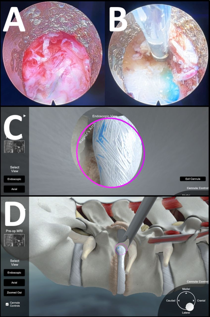
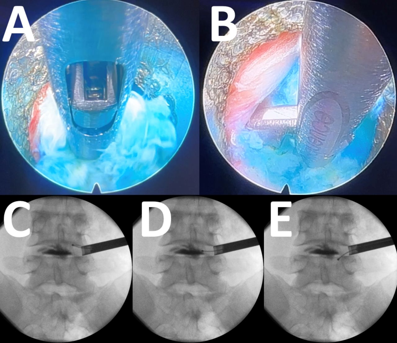
Initial endoscopy view of surgical target site at Kambin’s triangle obscured by numerous blood vessels, epidural fat, and frayed remnants of facet joint capsule and ligamentum flavum after reaming (A). The area is carefully approached once the location of the cannula is known by intraoperative imaging. The bevel of the cannula is rotated, and a curved probe is used to palpate and clear the surgical target site. The elastic feel of the disc can be well appreciated. Using bipolar electrocautery and radiofrequency probes, the blood vessels and reticular tissue can be ablated and swept away. The curved probe is fully deployed to reach the periphery of the surgical target site. By rotating the curved probe, rather than angling, the tip of the curved probe will sweep along the circumference of the endoscopic surgical site, acting as a blunt dissector as well as a feeler (B). A great degree of tactile feel is utilized. If a chromatodiscogram was performed, a blue hue may be appreciated at the site of an annular defect, further confirming the location of the disc, which may otherwise resemble a nerve. A guiding principle is that “everything is a nerve until proven otherwise.” Pictures of an interactive simulation are shown within the cannula, mimicking the endoscopic view (C) and the virtual view, zoomed out showing the surrounding anatomy (D). Virtual model is available at https://bhanimd.com/observer-transforaminal.
- Figure 7
An exercise module for practicing the rotation maneuver to reach out to the periphery of the endoscopic corridor and sweep from side to side without bending the instrument. To allow for a 180° rotation of the probe, the grip of the probe must be such that only fingertips are used to control the instrument (A and B). The radius from the center of the endoscopic corridor is controlled by the amount of the tip that is deployed from its housing, together with the depth of the entire probe relative to the endoscope. The exercise is to paint the entirety of the circle with the tip of the probe while using it through an endoscope rigidly fixed in space (C).
- Figure 8
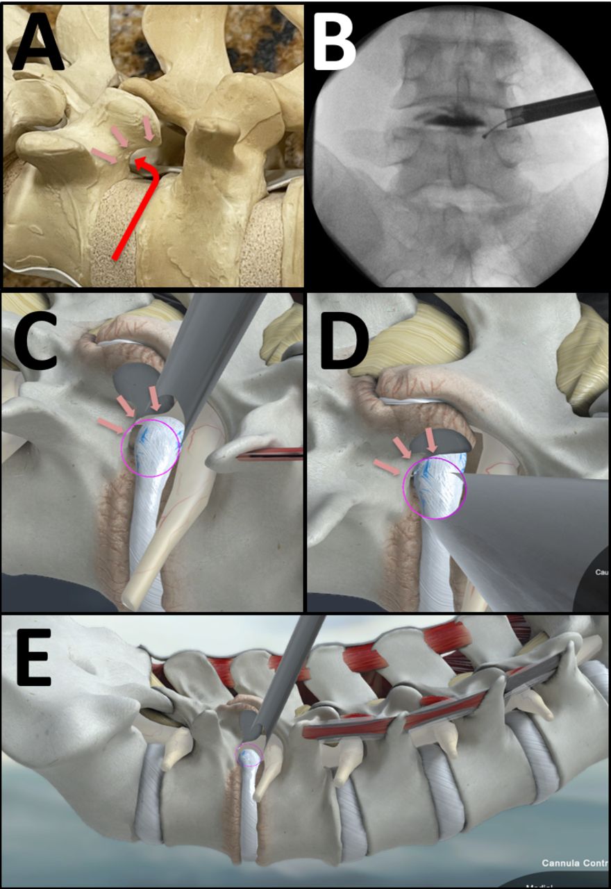
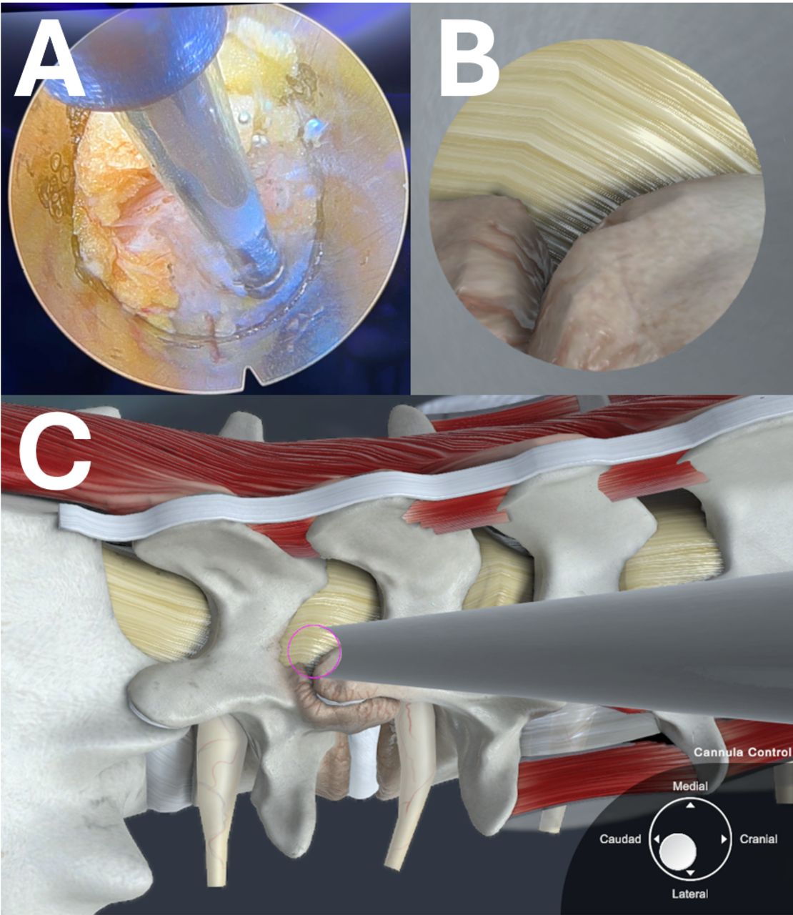
A key anatomic landmark is Wagner’s arch, the bony surface is composed of the caudal pedicle as it rises up and meets the superior articular process. It is resistant to degenerative changes and furthest away from the neuroforamen (A). It is readily identified by both palpation and intraoperative imaging (B). Using a curved bipolar probe, the bony surface can be palpated and then swept clear of epidural soft tissue. The base of the arch leads to the inferior edge of the disc space, which then leads to the neuroforamen and canal. Using a blunt probe such as a curved ball-tip feeler, the dural tube can be elevated away from the disc and posterior longitudinal ligament. The blunt probe is then passed over and caudal to the disc space. An expeditious AP image showing the probe caudal to the disc space confirms its location in 3-dimensional space (B). The position of the cannula in relation to Wagner’s arch is pictured in multiple angles (C, D, and E) using an interactive virtual model (https://bhanimd.com/observer-transforaminal).
- Figure 9
The ability to dissect and sweep tissues about the endoscopic surgical fields is paramount to successful endoscopic surgery. After using the bevel of the cannula to rotate and sweep open the surgical target site, tissues continue to creep into the surgical field. Using various tools, including both curved and articulating instruments, tissue planes can be developed as needed, structures can be nudged over for better visualization, epidural adhesions can be released, and ligamentum flavum and osteophytes can be separated from the dural membrane (A and B). Similar to open surgery techniques, the decompression can be assessed by passing an angled instruments above and below the nerve root. In endoscopic surgery, those instruments must be articulated, with rotation as the main means of sweeping and spanning the surgical site. The tactile feel of the decompression can be readily appreciated. Expeditious AP imaging of the probe at various anatomic locations can further confirm the extent of the decompression (C, D, E, and F).
- Figure 10
Once the cannula is optimally positioned and the surrounding epidural adhesions are released, endoscopic graspers and baskets can be used to mechanically remove loose disc fragments (A and B). In panel B, the caudal edge of the exiting nerve root can be seen in the upper left corner. When the exiting nerve root is in the surgical corridor, extreme care must be taken to avoid undue friction or compression of the dorsal root ganglion. The bevel of the cannula is rotated to isolate disc fragments and bring them within the surgical field until a thorough decompression is appreciated. A curved probe should readily pass along the anatomic location of the disc herniation, which can be readily confirmed by intraoperative imaging (C, D, and E).
- Figure 11
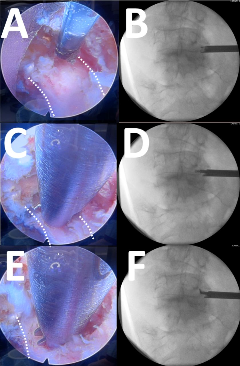
Endoscopic images with their corresponding anteroposterior (AP) C-arm image are shown for this right L4 to L5 foraminotomy. The exiting nerve root is outlined with dotted white lines (A). The curved radiofrequency probe can be seen entering the surgical field from above with the corresponding AP image confirming its anatomic location (B). An articulating curette is deployed between the exiting nerve root and the tip of the superior articular process (C and D). Rotating the articulating instrument sweep the dissection back and forth, identifying any residual areas of stenosis (E and F). Again, intraoperative AP imaging further confirms the anatomic location of the dissection.
- Figure 12
The interlaminar approach is best suited for L5 to S1 disc herniations, facet cysts, and stenosis, especially when adjacent to previous fusion (A and B). Using intraoperative imaging, including image guidance, the initial approach is through a small stab incision 1 to 2 cm from the midline along the path most appropriate to treat the pathology. For most disc herniation and stenosis, the disc space line is used. The initial dilator is first aimed at the base of the cephalad spinous process (C) where there is a relatively clear space to start the submuscular pocket. Sequential dilators are used to rapidly expand the surgical corridor. Using a sweeping and wanding motion, the dilators further clear the interlaminar window, the superior edge of the cephalad lamina, and the medial border of the facet joint (D, E, and F). Tactile feel, together with intraoperative imaging, is used to guide the initial dissection.
- Figure 13
The initial endoscopic view is obscured by dense muscle fibers and epidural fat (A). Using a combination of intraoperative imaging and tactile feel, the bony edge of the cephalad lamina and corner of the interlaminar window is exposed. A picture of the virtual model from the endoscope (B) as well as the zoomed-out view (C) shows the position of the surgical corridor (https://bhanimd.com/observer-interlaminar).
- Figure 14
Once the bony landmarks of the laminotomy window is exposed, the appropriate window is created using a combination of the endoscopic diamond burr, the ultrasonic bone resector, and/or Kerrison rongeurs (A and B). Panel B shows the endoscopic ultrasonic bone resector delineating the margins of the laminotomy window. The ligamentum flavum is thinned using graspers, baskets, and rongeurs. Once thin, the bevel tip of the cannula is rotated until a rent in the longitudinal fibers of the ligamentum flavum creates an opening into the canal, which often reveals epidural fat (C). Using various probes, including the articulating curette, epidural adhesions are released, and the dural tube is mobilized (D). The dorsal aspect of the dural tube and the lateral margin of the traversing nerve root can then be exposed (E). The disc can be seen with a blue hue at the inferior margin of the endoscopic window (E).
- Figure 15
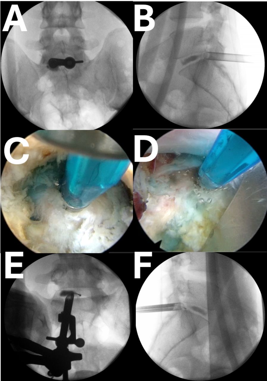
The cannula is carefully advanced aiming lateral and toward the pathology (A and B). By gently rotating the cannula, the dural tube can be mobilized and isolated away from the surgical site (C and D). A curved probe is usually needed to nudge the edge of the dura away from the edge of the cannula. Once the neural structures are protected, a discectomy and decompression are performed with various endoscopic instruments. The decompression is assessed by a combination of direct endoscopic visualization, palpation with curved instruments, and verification by intraoperative imaging (E and F). The probe should readily pass along all the areas of pathology.
- Figure 16
The biportal approach is simply an extension of the uniportal, interlaminar approach. After a reasonable amount of work is completed with the uniportal technique, a second incision is made at the desirable location, and a blunt dilator is inserted (A). The blunt dilator is then exposed under direct endoscopic view. This second port is then used for larger instruments entering from a different trajectory. As needed, the endoscope port and the instrument port can be swapped. Both the endoscopic port and the instrument port can accommodate working instruments such as a curette (C and D).
- Figure 17
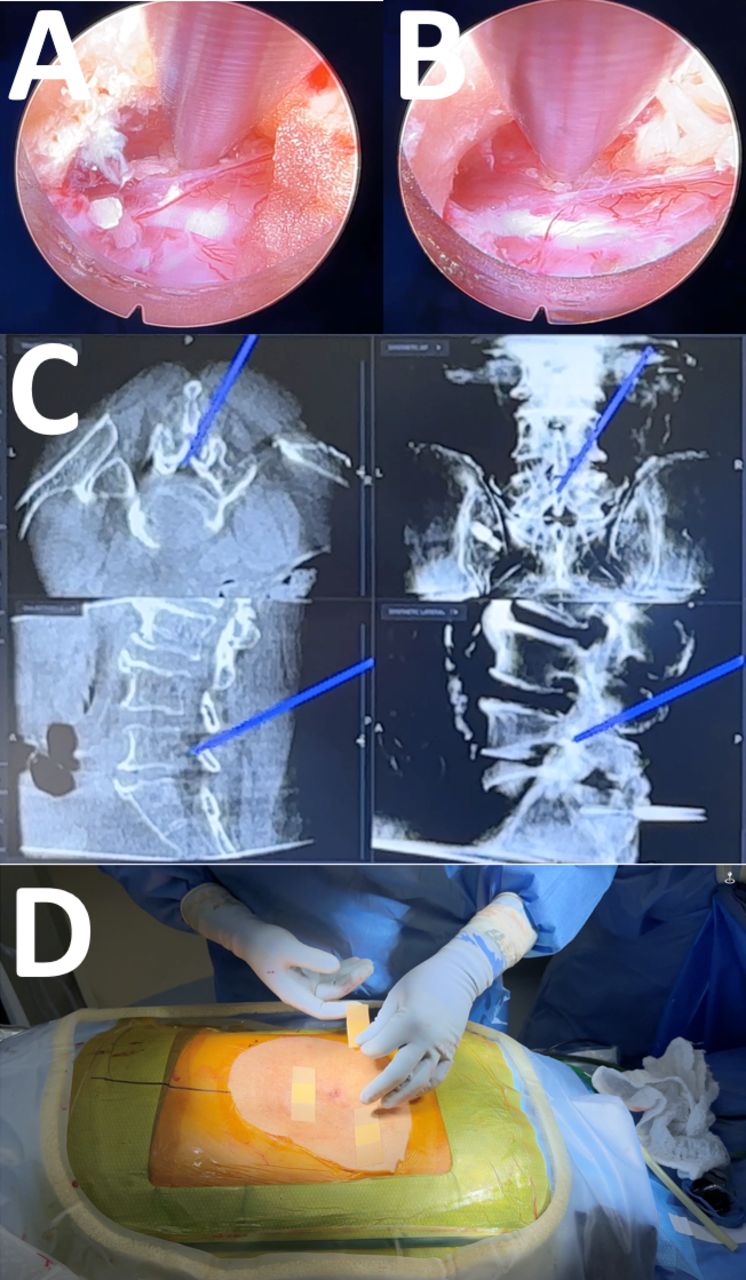
The interlaminar approach, whether uniportal or biportal, allows for contralateral decompression to be readily achieved through the over-the-top technique. The cannula is angled dorsally and medially to expose the base of the spinous process and ligamentum flavum. The ligamentum flavum is separated from the dural tube using curved probes. The ligament is excised using rongeurs and YAG-Holmium laser all the way to the contralateral recess, which seems more anterior than expected. Curettes and probes are used to elevate the dense ligamentous tissue from the dural tube, which can then be further resected with rongeurs. Again, probes should readily pass to the contralateral side, and any other pathology areas, without impediment, and confirmed with intra-operative imaging, either C-arm or navigation (C). Upon completion of the endoscopic procedure, the individual stab incisions are closed with a single subdermal bioabsorbable stitch, skin glue, and a small dressing (D).
- Figure 18
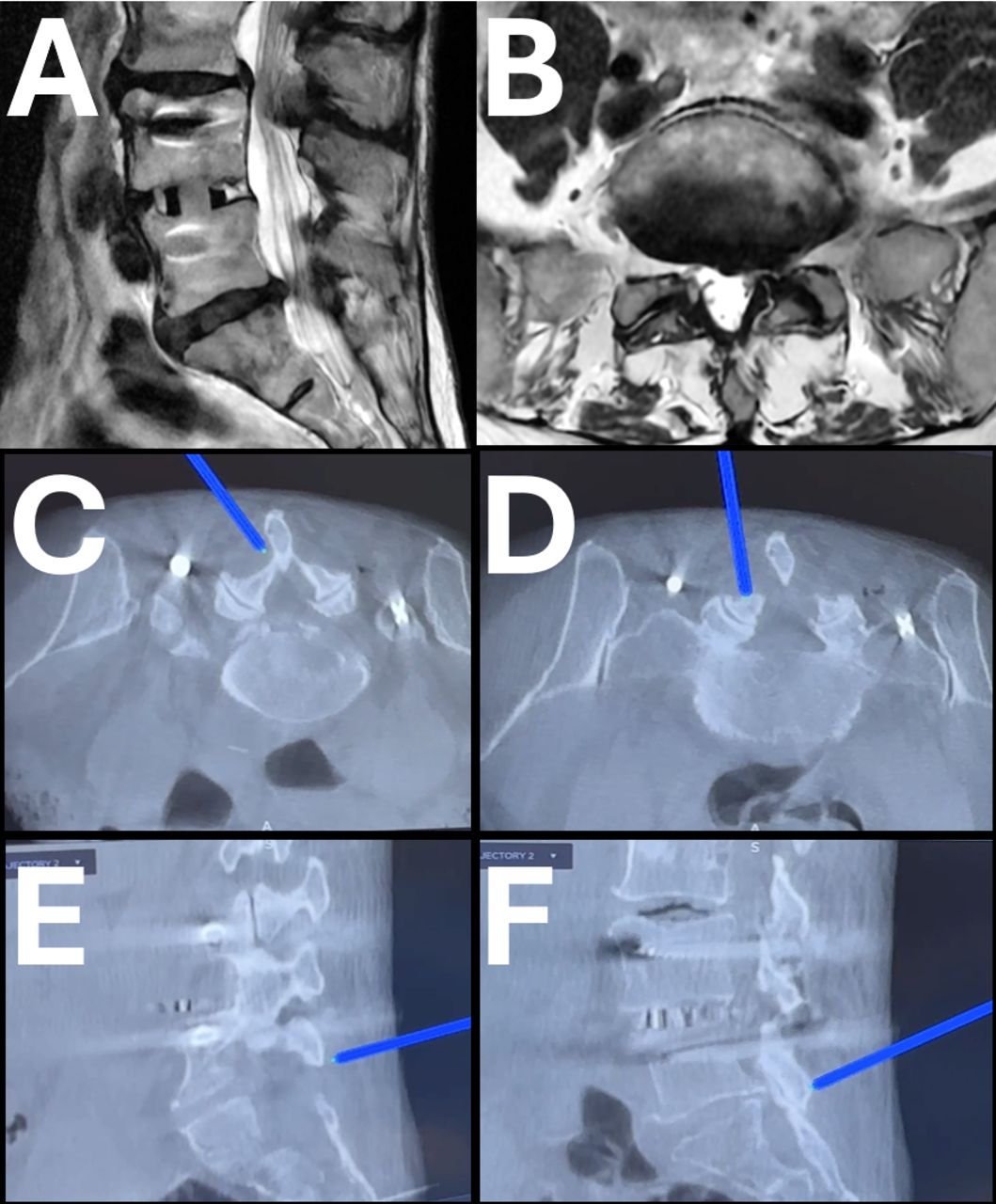
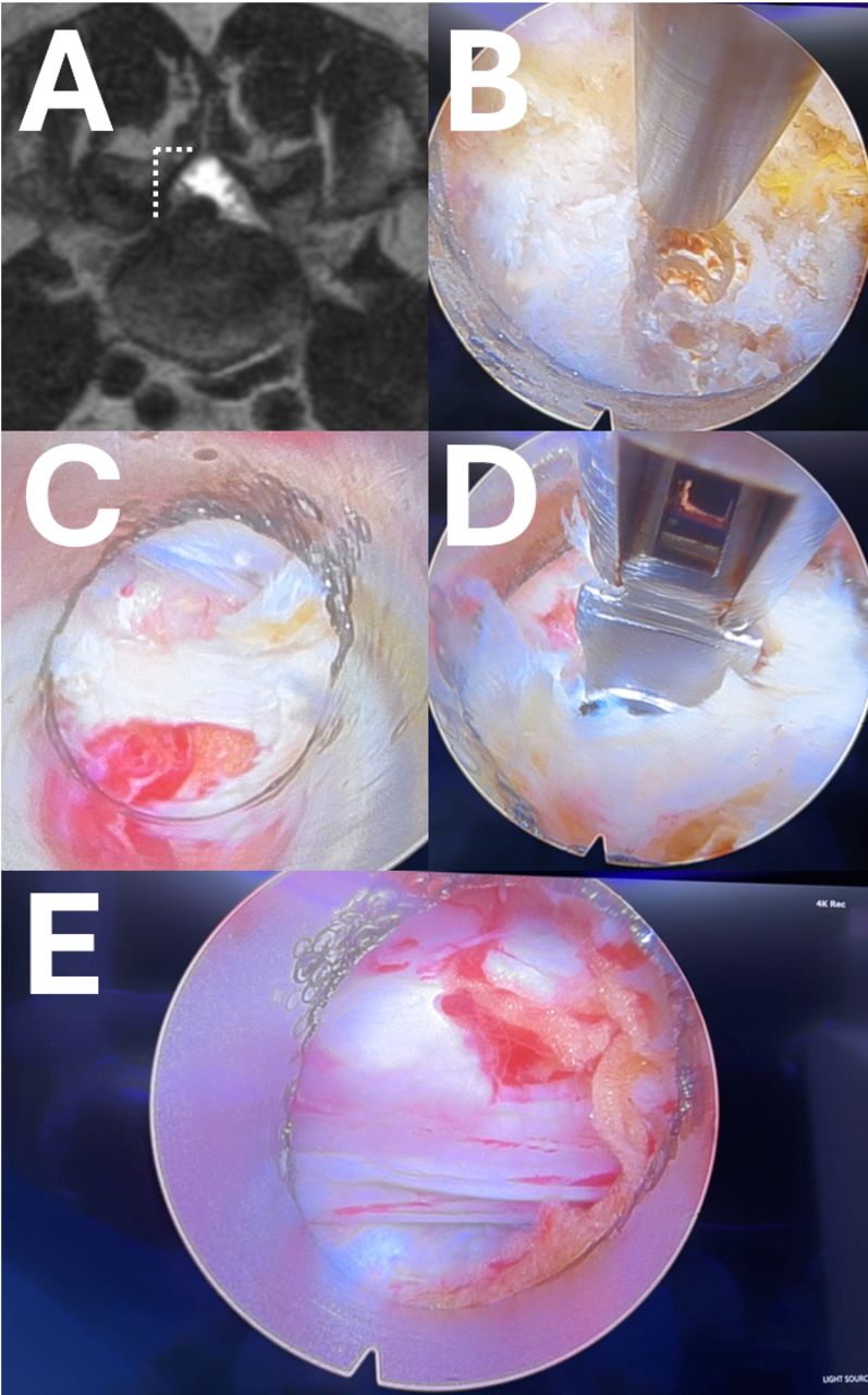
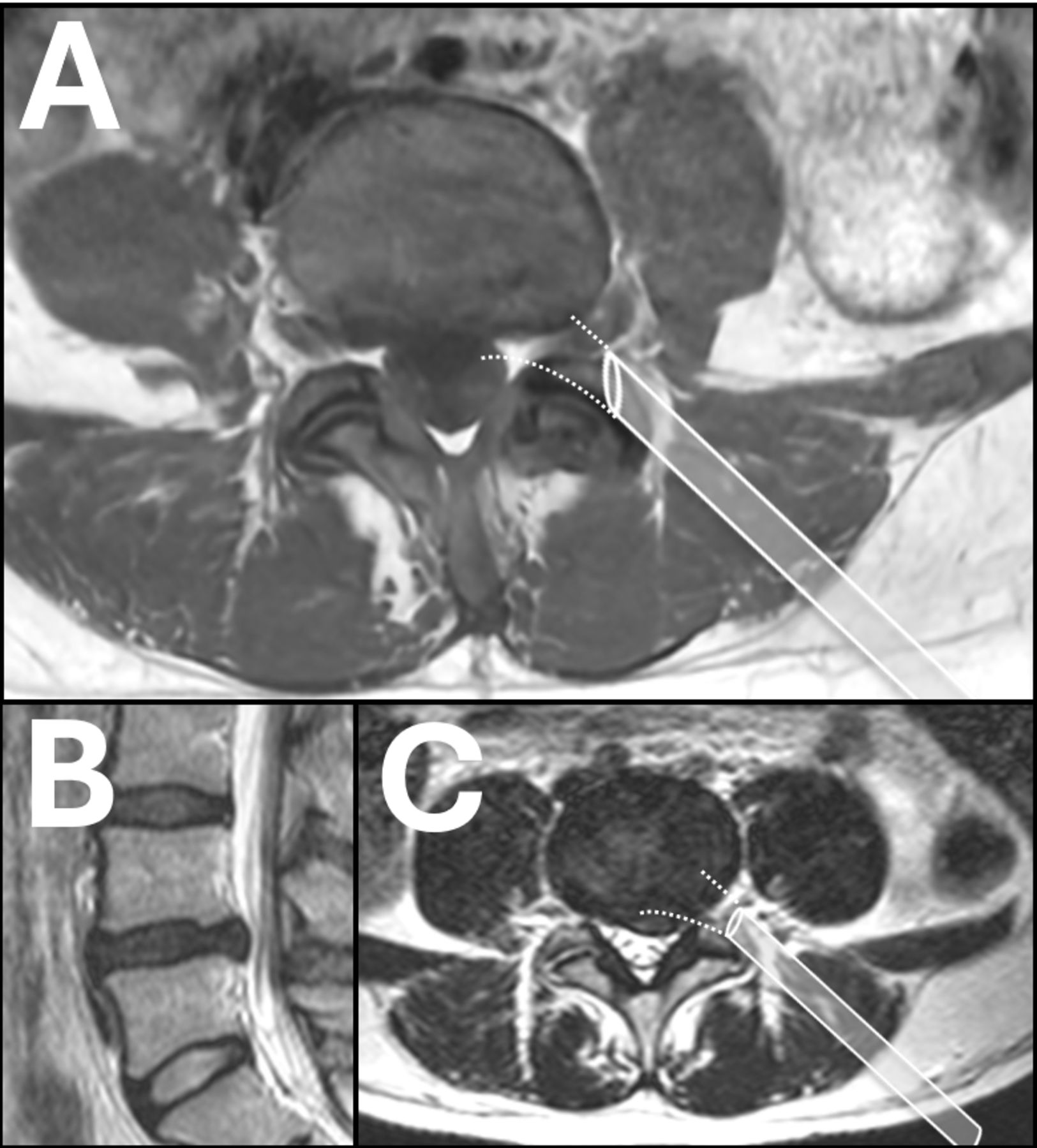
An important learning curve issue is choosing the wrong first case. Most commonly, surgeons will choose a foraminal disc herniation for the first transforaminal case. While a foraminal disc herniation is well treated with lumbar endoscopic spine surgery, it is also very difficult technically. The endoscope, which is angled at 30°, is usually docked medial to the foraminal disc herniation (A). To reach the pathology, the surgeon must work with an endoscope facing in the opposite direction of its design, rendering the image upside down and backward. For experienced endoscopic surgeons, this shift in the visual field can be readily accommodated, although still challenging. Another common misconception is that the contained disc is easier to treat than an extruded herniated disc (B). In actuality, the contained disc herniation that is broad, extending to the contralateral side, is another difficult learning curve case. Again, it is difficult to reach past the midline from a transforaminal approach (C). Furthermore, the lack of a tail that an extruded disc might have is usually absent from a contained disc herniation, making it difficult to know how disc to remove.


In this issue


Jump to section
Related Articles
Cited By...
- No citing articles found.